
Dielectric barrier discharge lamp and method and circuit for igniting and operating said lamp

a technology of dielectric barrier and discharge lamp, which is applied in the direction of electric discharge lamps, energy-saving lighting, sustainable buildings, etc., can solve the problems of long ignition delay after the application of voltage to the electrodes of the lamp, sacrificing the maximum possible luminous efficiency, and affecting the operation of the lamp in the dark

Inactive Publication Date: 2004-09-23
PATENT TREUHAND GESELLSCHAFT FUR ELECTRIC GLUEHLAMPEN MBH
View PDF17 Cites 8 Cited by
  • Summary
  • Abstract
  • Description
  • Claims
  • Application Information

AI Technical Summary

Benefits of technology

[0020] The advantage of this method consists inter alia in facilitating the ignition of the main discharge by means of the already burning auxiliary discharge. As a result, the operating voltage need not be increased during the ignition phase, even in darkness. Consequently, the extra outlay on higher electric strength otherwise required when designing the lamp voltage generator supplying the operating voltage can be avoided. Only the drive circuit for the electrode gap for igniting the auxiliary discharge must be designed to be of suitably high electric strength, in order to ensure reliable ignition. However, the voltage level required for igniting the auxiliary discharge can be limited by relatively simple measures. Thus, the electrode gap is preferably selected to be smaller than the distance from the nearest electrode, or smaller than the spacing of the electrodes of opposite polarity between which the main discharge burns in normal operation. This ensures that the ignition voltage of the auxiliary discharge is lower than the ignition voltage of the main discharge without the aid of the auxiliary discharge. Moreover, it is possible even in the case of the ends of the component electrodes bounding the electrode gap to dispense entirely with the dielectric impediment (dielectrically unimpeded auxiliary discharge), or for only one end to be dielectrically impeded (auxiliary discharge dielectrically impeded at one end). Such a dielectrically unimpeded auxiliary discharge has the advantage of a particularly low ignition voltage, although this is at the cost of a more intense contamination through sputter processes in the region of the two component electrode ends. It can therefore also be advantageous in this regard to provide the complete gap, but at least the component electrode ends, with a dielectric layer (auxiliary discharge impeded dielectrically at both ends), and to accept the somewhat higher ignition voltage resulting thereby for the auxiliary discharge. The power turnover in the auxiliary discharge, which is substantially lower by comparison with the main discharge, is likewise also advantageous. The drive circuit for the auxiliary discharge can therefore be of correspondingly smaller dimensions, and therefore more cost-effective.
[0022] In normal operation, the value of the voltage between the two component electrodes is preferably selected to be lower than the ignition voltage and / or the maintenance voltage of the auxiliary discharge. The auxiliary discharge is therefore extinguished in normal operation. This has the advantage that the main discharge and the homogeneity of the luminance of the lamp are not influenced as a whole and, moreover, the drive circuit for the auxiliary discharge is de-energized in normal operation. It is particularly preferred to select the value of the voltage between the two component electrodes to be sufficiently low in normal operation in order to avoid any influence being exerted on the main discharge. It has proved to be particularly advantageous, in normal operation, to keep the two component electrodes at substantially the same electric potential.

Problems solved by technology

However, the long ignition delay after the application of the voltage to the electrodes of the lamp is disadvantageous when the lamp is in the dark, for example inside an LCD display.
It is disadvantageous that because of the coating for lowering the ignition voltage the dielectric surface has no phosphor layer, as a result of which a portion of the maximum possible luminous efficiency is sacrificed.
Ignition problems also arise with this lamp in the dark, for example inside an OA appliance.
However, the voltage level required for igniting the auxiliary discharge can be limited by relatively simple measures.

Method used


Image

  • Dielectric barrier discharge lamp and method and circuit for igniting and operating said lamp
  • Dielectric barrier discharge lamp and method and circuit for igniting and operating said lamp

Examples


Embodiment Construction

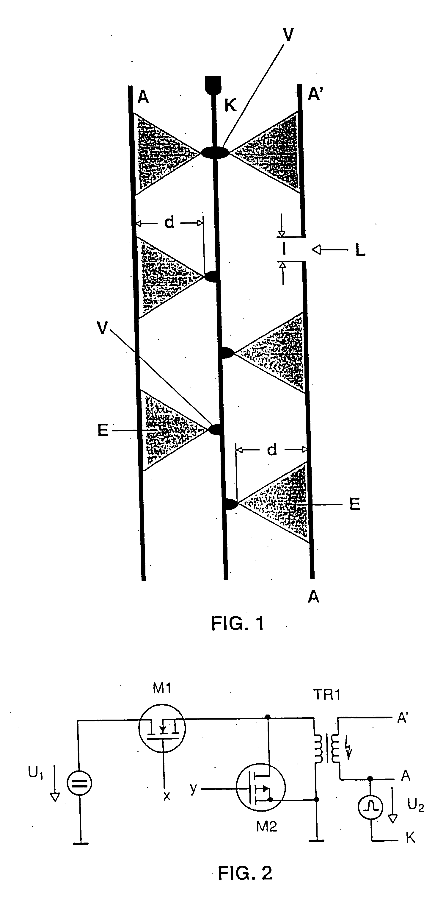
[0031] FIG. 1 shows a detail of an electrode design for a flat dielectric barrier discharge lamp. The electrode design is intended for operation with unipolar voltage pulses, and has for this purpose a number of anode tracks A and cathode tracks K that are printed on the base plate of the flat lamp (not illustrated here). There is always one cathode track arranged between two anode tracks in this case. For the sake of clarity, only one detail is illustrated with two anode tracks and one cathode track. The electrode tracks are covered with a thin glass layer (not illustrated) acting as dielectric barrier. Each cathode track K has projections V on both sides, which serve as means for locating the triangular partial discharges E burning during operation. The right-hand anode track in FIG. 1 is divided into the two component anode tracks A and A' by the gap L, which interrupts this anode track. The length 1 of the electrode gap L is approximately 0.8 mm. Located to the left of the catho...


PUM


Abstract

An elongated electrode of a dielectric barrier discharge lamp is divided into two component electrodes (A, A') by a gap (L). The two component electrodes (A, A') are driven in an ignition phase in such a way that an auxiliary discharge that facilitates the ignition of the main discharge (E) in the region of the electrode gap (L), in particular when the lamp is in the dark. In normal operation, the component electrodes (A, A') are driven in such a way that they contribute to the generation of the main discharge (E).

Description

[0001] The invention relates to a dielectric barrier discharge lamp and a method for igniting and operating this lamp, and to a circuit arrangement suitable for carrying out the method.[0002] Dielectric barrier discharge lamps are sources of electromagnetic radiation based on dielectrically impeded gas discharges.[0003] A dielectric barrier discharge lamp necessarily presupposes at least one so-called dielectrically impeded electrode. A dielectrically impeded electrode is separated from the interior of the discharge vessel by means of a dielectric barrier. This dielectric barrier can be designed, for example, as a dielectric layer covering the electrode, or it is formed by the discharge vessel of the lamp itself, specifically when the electrode is arranged on the outer wall of the discharge vessel.[0004] Because of the dielectric barrier, the operation of such lamps requires a time-variable voltage between the electrodes, for example a sinusoidal AC voltage or a pulsed voltage, as d...

Claims


Application Information

Patent Timeline
Patent Type & Authority Applications(United States)
IPC IPC(8): H01J65/00H01J65/04H05B41/24H05B41/28
CPCH01J65/046Y02B20/22H05B41/2806H05B41/24Y02B20/00H05B41/288
Inventor SCHALLMOSER, OSKAR
Owner PATENT TREUHAND GESELLSCHAFT FUR ELECTRIC GLUEHLAMPEN MBH
Learn More