Dust collection system

a dust collection and cyclonic separator technology, applied in the direction of vortex flow apparatus, filtration separation, separation process, etc., can solve the problems of cumbersome, inconvenient, cumbersome, etc., and achieve compact and efficient dust collection, reduce the inherent fire or explosion hazard of dust collection equipment, and reduce power requirements

Inactive Publication Date: 2004-09-30
WITTER ROBERT M
View PDF51 Cites 34 Cited by
  • Summary
  • Abstract
  • Description
  • Claims
  • Application Information

AI Technical Summary

Benefits of technology

0010] It is another object to provide dust collection system which reduces the power requirement, and also reduces the inherent fire or explosion hazard of the dust collection equipment.
0011] According to an aspect of the invention, a compact and efficient dust collection system is provided for collecting production dust from a floor sander or other source machine that generates such dust in a production operation. The source machine has an internal blower for picking up the dust that the machine generates and exhausting the dust, entrained in a stream of air, to an exhaust outlet on the source machine. A compact, low-volume cyclonic separator is mounted on the source machine. The cyclonic separator has an inlet portion at the top, and an inner tubular baffle coaxial with the upper inlet portion and having open ends. The inlet portion and inner baffle define between them an annular inlet space. A frustoconic portion beneath the upper inlet portion and having a wide end joined at the inlet portion and this descends to a narrow lower end, where there is a dust outlet duct. An inlet duct receives the air flow and exhaust dust from the machine and injects this air flow into the annular inlet space. a pleated air filter, or equivalent air c

Problems solved by technology

For hand-held and mobile power tools, such as floor sanding equipment, the associated dust collection systems currently in use are cumbersome, impractical, or inadequate.
These maintenance-intense systems blind or clog readily, which reduces the pickup volume at the source, allowing the particulate waste to become airborne or to interfere with the operation.
These systems do not deliver the necessary air volume to the tool because of intrinsic mechanical problems of delivering air through the extended lengths of flexible tubing.
Frictional losses in ducts increase exponentially with air velocity, so very wide diameter tubing is used, and this relatively large tubing, being quite cumbersome, hinders the operator in using the machine.
In addition, because all of the air that exits the sanding machine has to be carried all the way out to a remote collection station, the flexible hoses are required to have a rather

Method used


Image

  • Dust collection system
  • Dust collection system
  • Dust collection system

Examples


Embodiment Construction

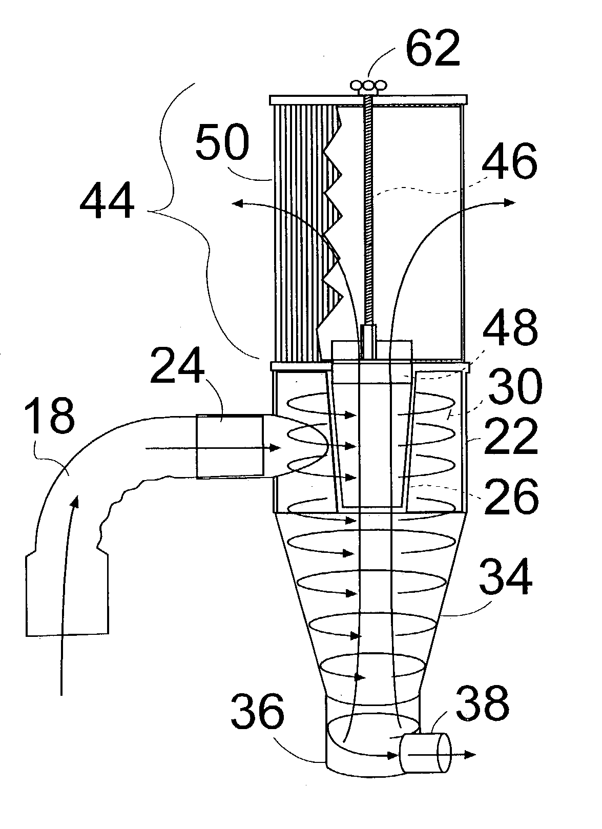
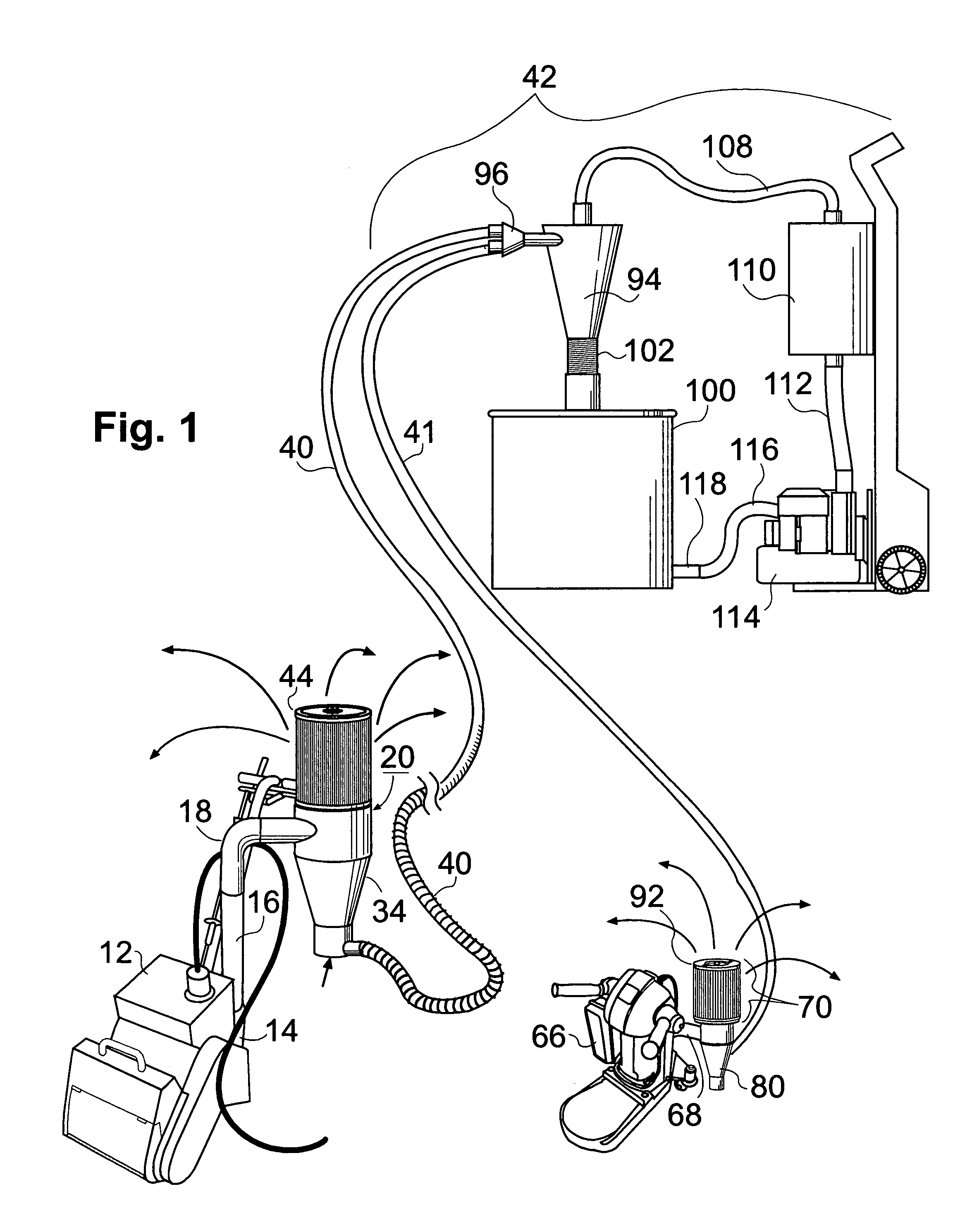
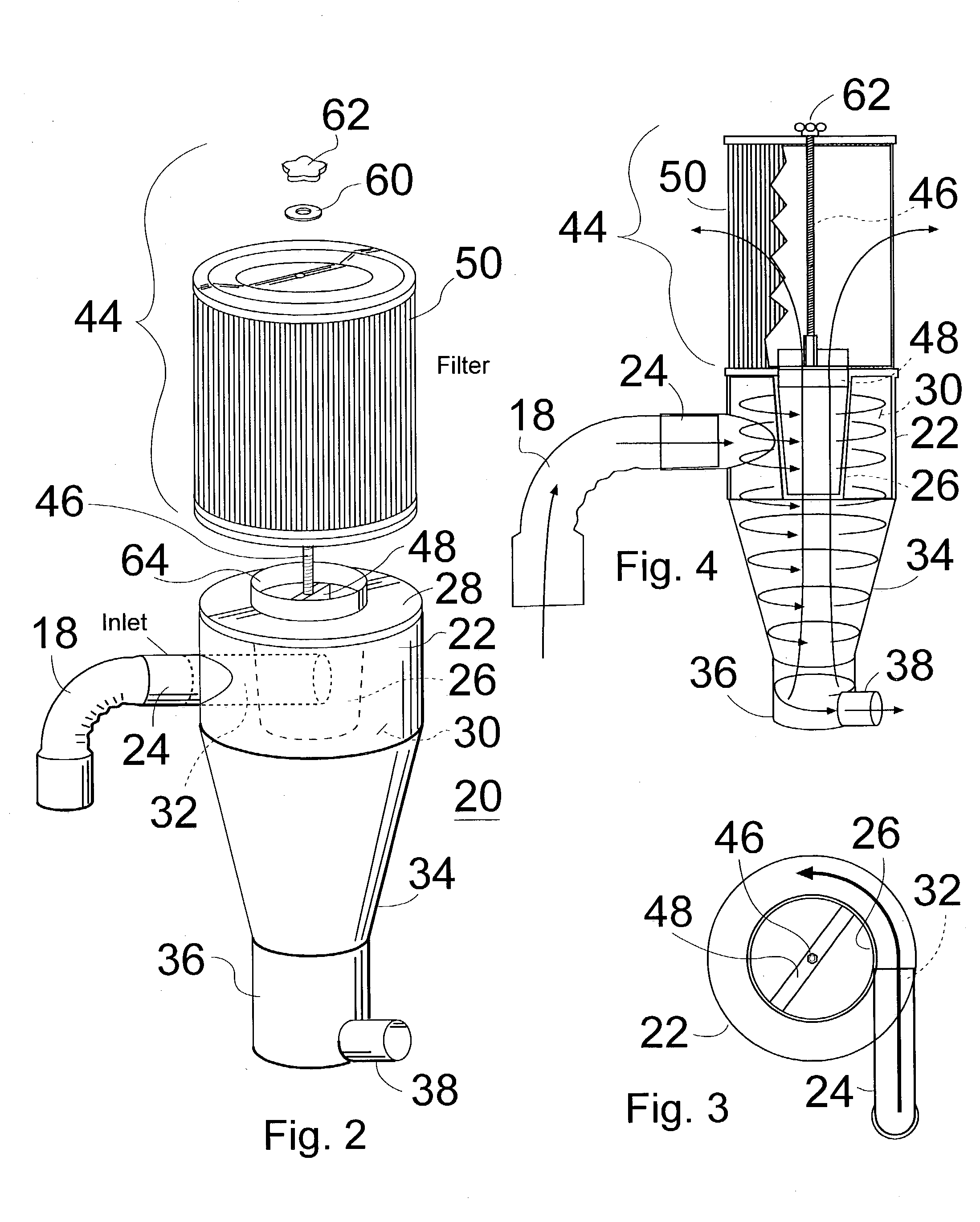
[0024] Now with reference to the Drawing, FIG. 1 shows a dust collection system according to an embodiment of this invention in which dust is separated from the air flow at the tool or machine, with the air being cleaned and returned to the ambient in the vicinity of the tool and with the dust being transported on a smaller volume air flow to a remote collection site.

[0025] a dust generating machine or tool, here a floor sanding machine 12, has a built-in exhaust blower 14 that vacuums up any sanding dust produced and discharges it upwards through an upright pipe 16. An inlet-connection ell 18 is mounted at a top end of the pipe 16, and a compact cyclonic separator 20 is supported on the ell 18. In this embodiment, the cyclonic separator 20 has a barrel or drum 22 at its upper end. The cyclonic separator can be described with additional reference to FIGS. 2, 3, and 4. An inlet pipe 24 that fits into the ell 18 extends though the barrel 22, as will be discussed later. a tubular baffl...


PUM

PropertyMeasurementUnit
Diameteraaaaaaaaaa
Volumeaaaaaaaaaa
Flexibilityaaaaaaaaaa

Abstract

A dust collection system for portable sanding or grinding equipment employs a cyclone separator mounted directly on the tool or machine, with a dust outlet duct at the narrow lower end of the cyclone, and a cartridge air filter mounted on the top of the cyclone. The filter returns the air flow from the machine to the ambient air in the vicinity of the tool. The dust is concentrated in the cyclone, and a small volume air flow then moves the dust through an elongated flexible hose or duct to a remote dust collection station. An air pump at the remote dust collection station provides sufficient air flow to draw the small volume of air plus entrained dust from the tool-mounted cyclonic separator. A cyclonic separator at the remote station separates this dust from the air flow and deposits it in a collection tank or drum.

Description

[0001] This invention is directed to devices and equipment for removing process dust coming from a dust generating machine, such as a sanding machine, and separating the dust from exhaust air flowing from the machine. The invention is more specifically directed to a compact and efficient system for removing the production dust from the work area to a dust collection station located beyond the work area, and which removes a majority of the air from the dust flow.[0002] For many types of machines for processing a workpiece, some means has to be provided to dispense with the grindings, chips, and particulate matter that is generated by the machine during operation. For example, in the case of wood working machines, such as sanders, joiners, and the like, wood that is removed from a workpiece has to be collected and removed from the work area so as to avoid either a breathing hazard for the workman or a fire hazard. More specifically, in the case of portable equipment, such as floor san...

Claims


Application Information

Patent Timeline
IPC IPC(8): B01D50/00B04C5/04B04C5/13B04C9/00B24B7/18B24B55/10
CPCB01D50/002B04C5/04B04C5/13B24B55/10B04C2009/002B24B7/18B04C9/00B01D50/20
Inventor WITTER, ROBERT M.
Owner WITTER ROBERT M
Why Eureka
Try Eureka