Power-on reset circuit

Inactive Publication Date: 2004-10-28
SHARP KK
View PDF4 Cites 12 Cited by
  • Summary
  • Abstract
  • Description
  • Claims
  • Application Information

AI Technical Summary

Benefits of technology

0015] By way of a second feature, according to the POR circuit of the invention, the reset pulse generation circuit outputs the second output voltage to the output node and reduces the set value of the charge level. More specifically, in the POR circuit according to the second feature, the reset pulse generation circuit comprises an inverter circuit in an initial stage for inputting the charge level of the capacitor as an input voltage and outputs a negation logic level thereof, and a transistor for imparting hysteresis characteristics to the inverter circuit.
0016] According to the POR circuit according to the second feature of the invention, ordinarily a plurality of circuits synchronously starts a reset operation after the reset pul

Problems solved by technology

However, in a POR circuit of the above-described type composed only of such the capacitor charge circuit, a problem occurs in that a reset pulse is not generated when a boosting speed rate of the power supply voltage is later than a charge time constant of the capacitor.
Since discharging means of the capacitor is not provided, the

Method used


Image

  • Power-on reset circuit
  • Power-on reset circuit
  • Power-on reset circuit

Examples


Embodiment Construction

)

[0024] Referring to the accompanying drawings, an embodiment of a POR circuit of the invention (which hereafter will also be referred to as an "inventive circuit") will be described hereinbelow.

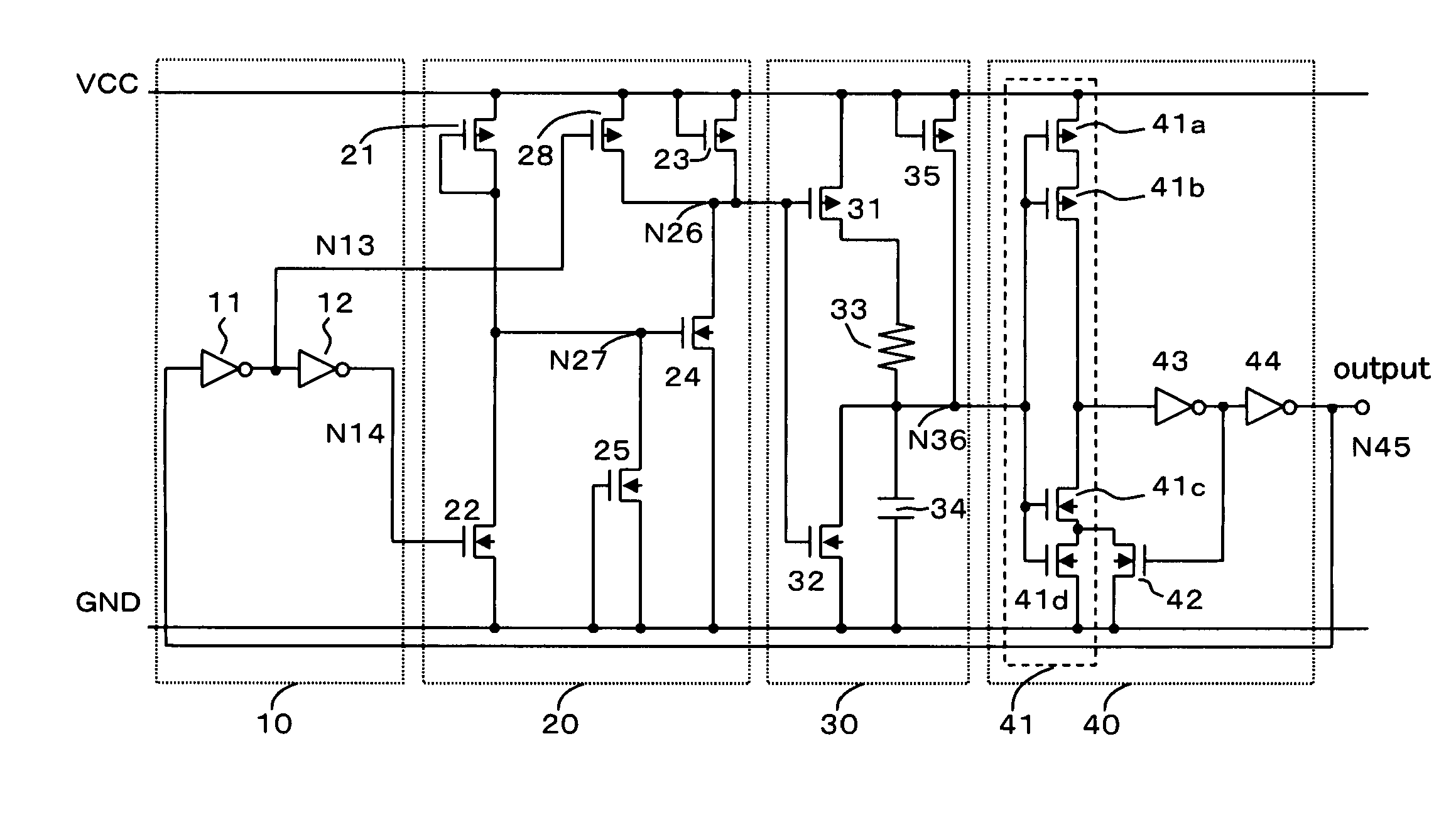
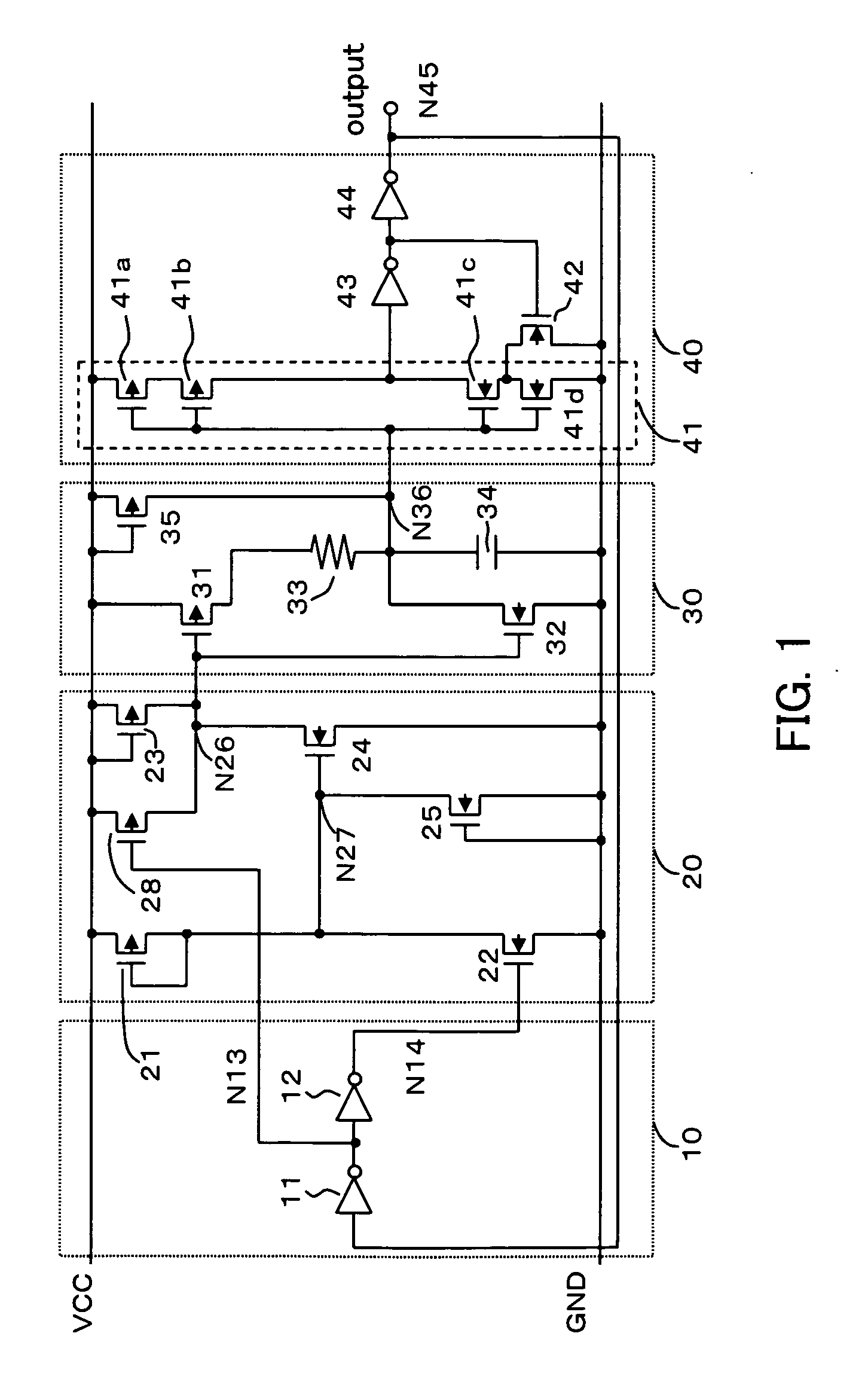
[0025] Referring to FIG. 1, the inventive circuit is composed of a power supply voltage detection circuit 20, a capacitor charge / discharge circuit 30, a reset pulse generation circuit 40, and a power reduction circuit 10.

[0026] The power supply voltage detection circuit 20 detects a rise of a power supply voltage Vcc to a predetermined voltage V0 or higher and then causes a logical level of a first internal node N26 to change from a high level (first level) to a low level (second level). More specifically, as shown in FIG. 1, the power supply voltage detection circuit 20 is composed of three P-type MOSFETs (each of which hereinbelow will be referred to as a "PMOS") 21, 23, and 28 and three N-type MOSFETs (each of which hereinbelow will be referred to as a "NMOS") 22, 24, and 25. The PMOS 21 ...


PUM


Abstract

A power-on reset circuit comprises a power supply voltage detection circuit that detects a rise of a power supply voltage and that changes a logic level of a first internal node; a capacitor charge/discharge circuit that charges and discharges a capacitor according to the first internal node level and that in an event that the power supply voltage is reduced, discharges the capacitor to follow the event; and a reset pulse generation circuit that before the power supply voltage rises higher than the predetermined voltage, outputs a first output voltage to an output node and that after the power supply voltage has risen higher than the predetermined voltage, outputs a second output voltage to the output node upon detecting that a charge level of the capacitor has become higher than a charge level detection voltage.

Description

[0001] 1. Field of the Invention[0002] The present invention relates to a power-on reset circuit (which hereinbelow will be referred to as a "POR circuit") for generating a reset pulse by a sensing a power supply voltage rise at a power-on time. More particularly, the invention relates to a POR circuit to be provided to reset another circuit within a same integrated circuit in a semiconductor integrated circuit.[0003] 2. Description of Related Art[0004] Conventional POR circuits have a capacitor charge circuit composed of a charging capacitor and a resistor or a constant current source, and outputs a reset pulse at a power-on time. However, in a POR circuit of the above-described type composed only of such the capacitor charge circuit, a problem occurs in that a reset pulse is not generated when a boosting speed rate of the power supply voltage is later than a charge time constant of the capacitor. Conventional techniques dealing with the problem include, for example, a technique di...

Claims


Application Information

Patent Timeline
IPC IPC(8): H03K17/22H03K17/687
CPCH03K17/223
Inventor AKAMATSU, TETSUYADOI, HIROKIINAMORI, MASANORI
Owner SHARP KK
Why Eureka
Try Eureka