Optical pickup device, optical information recording and reproducing apparatus, expander lens, coupling lens and chromatic aberration correcting optical element

a pickup device and optical element technology, applied in the direction of optical beam sources, door/window protective devices, instruments, etc., can solve the problems of insufficient value of optical disc player products, inability to conduct proper recording/reproducing of information for high density optical discs, and large focus error generation

Inactive Publication Date: 2004-10-28
KONICA MINOLTA OPTO
View PDF10 Cites 59 Cited by
  • Summary
  • Abstract
  • Description
  • Claims
  • Application Information

AI Technical Summary

Problems solved by technology

The reason for the foregoing is that a focus error is generated to be large by even a slight change of wavelength, because wavelength dispersion of lens material in the violet area becomes extremely great.
Only ability to conduct proper recording / reproducing of information for high density optical disc is not a sufficient value of an optical disc player product.
However, this method is disadvantageous for downsizing, and the cost thereof is increased.
However, in the drawings and description in the aforesaid Patent Application, there is no disclosure about how to correct spherical aberration in the case of conducting recording / reproducing of information for high density optical disc.
In particular, if a numerical aperture of the objective lens unit in the case of conducting recording / reproducing of information for a high density disc is large, spherical aberration is easily generated even when a thickness of the protective layer of the first optical disc is changed slightly from a standard thickness of a protective layer in design of the objective lens unit.
Therefore, there is a possibility that a yield rate in mass production of optical discs is adversely affected, because it is necessary to control accurately a standard thickness of a protective layer of the optical disc.
Therefore, if a numerical aperture of the objective lens unit in the course of conducting recording / reproducing of information for a high density optical disc is great, a change of spherical aberration grows greater, thus, a temperature range for the objective lens unit to be used becomes extremely narrow, which causes a problem in practical use.
Further, when a numerical aperture of the objective lens unit is great, spherical aberration changes in the case of occurrence, in the plastic lens, of refractive index distribution following upon temperature distribution in the optical axis direction and upon temperature distribution that is rotationally-symmetric about the optical axis, also cause a problem.
As a result, there has been a problem that a position of an object point of the objective lens is changed, and spherical aberration is deteriorated.
However, in the case of a high density optical disc, optical specifications such as a thickness of a protective layer and a numerical aperture are still in the actual circumstances that they are not determined, because light sources capable of being used are limited, with an exception that the wavelength to be used for recording / reproducing of information has mostly been determined.
Therefore, with respect to the objective lens used for conducting recording / reproducing of information for a high density optical disc, it is necessary to allow tediousness to be in design to a certain extent, and in this case, it is extremely difficult, on the point of aberration characteristics, to conduct recording / reproducing of information even for DVD and CD by using the common objective lens.
However, radius of curvature of the optical surface of the objective lens for a high density optical disc tends to be small because the objective lens needs a great power.
As stated above, optical specifications such as a thickness of a protective layer and a numerical aperture are not yet determined, because light sources capable of being used are limited, although the wavelength to be used for recording / reproducing of information has been determined substantially.

Method used


Image

  • Optical pickup device, optical information recording and reproducing apparatus, expander lens, coupling lens and chromatic aberration correcting optical element
  • Optical pickup device, optical information recording and reproducing apparatus, expander lens, coupling lens and chromatic aberration correcting optical element
  • Optical pickup device, optical information recording and reproducing apparatus, expander lens, coupling lens and chromatic aberration correcting optical element

Examples


example 1

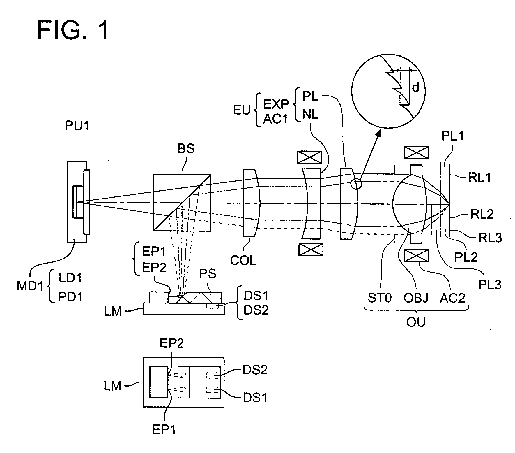
[0343] Example 1 is represented an optical system suitable as expander lens EXP and objective lens OBJ in optical pickup device PU1, and the optical system is composed of objective lens OBJ representing a plastic lens whose aberration correction is optimized for wavelength 405 nm and for a protective layer with a thickness 0.6 mm and of expander lens EXP composed of two plastic lenses including negative lens NL and positive lens PL.

[0344] Table 1 shows specific lens data of the optical system, FIG. 7 shows an optical path diagram for conducting recording / reproducing of information for high density optical disc HD, FIG. 8 shows an optical path diagram for conducting recording / reproducing of information for DVD and FIG. 9 shows an optical path diagram for conducting recording / reproducing of information for CD.

1TABLE 1 f1 = 2.308, NA1 = 0.65, .lambda.1 = 405 nm, m1 = 0.00, n1 = 10, d2 = 2.000, d6 = 1.059, d7 = 0.6 f2 = 2.385, NA2 = 0.63, .lambda.2 = 655 nm, m2 = -0.02, n2 = 6, d2 = 1.5...

example 2

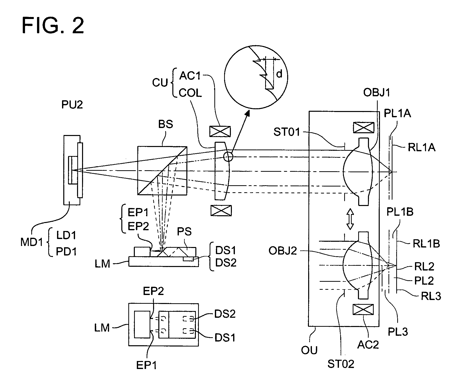
[0353] Example 2 is represented by an optical system suitable as collimator lens COL, first objective lens OBJ1 and second objective lens OBJ2 in optical pickup device PU2, and the optical system is composed of first objective lens OBJ1 representing a plastic lens of a two-group two-element structure optimized in terms of aberration correction for wavelength 405 nm and a protective layer with thickness 0.1 mm, second objective lens OBJ2 representing a plastic lens optimized in terms of aberration correction for wavelength 405 nm and a protective layer with thickness 0.6 mm and of collimator lens COL representing a plastic lens.

[0354] Table 2 shows specific lens data of the optical system composed of first objective lens OBJ1 and collimator lens COL, Table 3 shows specific lens data of the optical system composed of second objective lens OBJ2 and collimator lens COL, FIG. 12 shows an optical path diagram for conducting recording / reproducing of information for the first high density o...

example 3

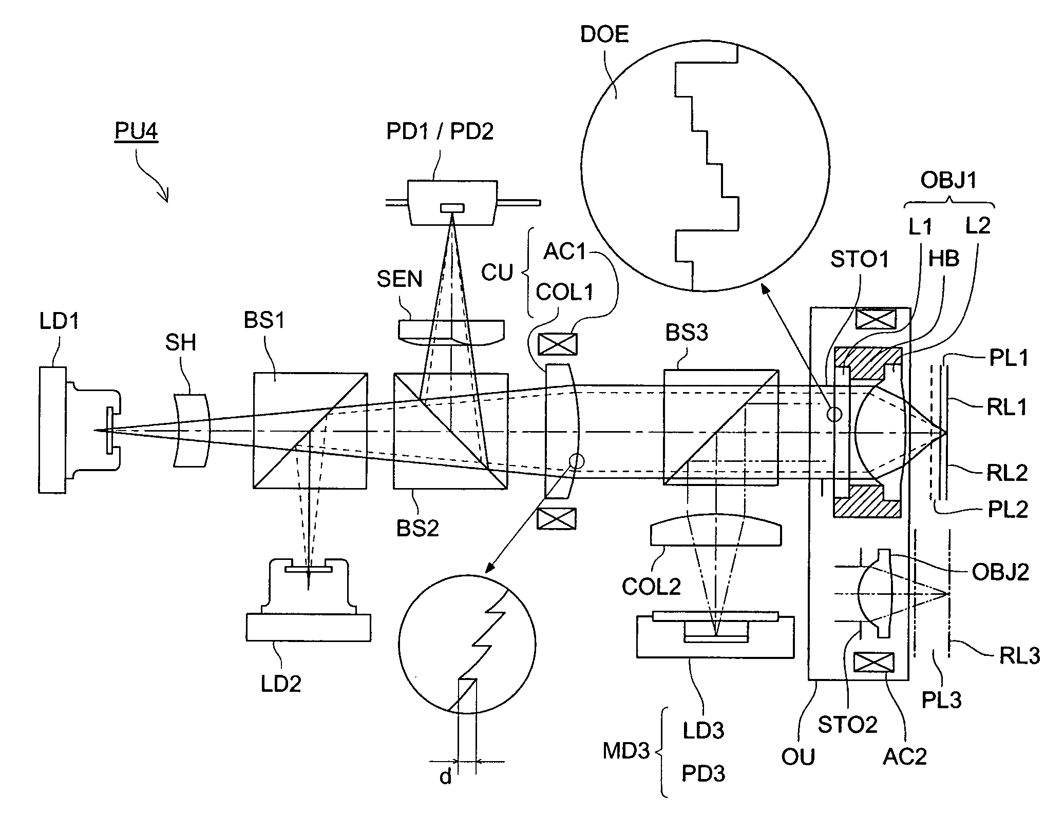
[0367] Example 3 is represented by an optical system suitable ad the first collimator lens COL1 and the first objective lens OBJ1, and it is composed of the first objective lens OBJ1 having interchangeablility for high density optical disc HD with standards of wavelength 405 nm, protective layer thickness 0.1 mm and numerical aperture 0.85 and for DVD with standards of wavelength 655 nm, protective layer thickness 0.6 mm and numerical aperature 0.65 and of the first collimator lens COL1 which is a plastic lens whose optical surface on the first objective lens OBJ1 side is made to be a differactive surface.

[0368] Table 4 shows specific lens data of this optical system, and FIG. 19 shows an optical path diagram.

4TABLE 4 f1 = 1.765, NA1 = 0.85, .lambda.1 = 405 nm, m1 = 0.00, n1 = 3, d0 = 19.034, d6 = 0.531, d7 = 0.1 f2 = 1.830, NA2 = 0.65, .lambda.2 = 655 nm, m2 = 0.00, n2 = 2, d0 = 24.445, d6 = 0.300, d7 = 0.6 Paraxial value Surface No. r (mm) d (mm) N.lambda.1 N.lambda.2 vd 0 --d0 --...


PUM

PropertyMeasurementUnit
first wavelength λ1aaaaaaaaaa
wavelengthaaaaaaaaaa
depthaaaaaaaaaa

Abstract

An optical pickup apparatus includes first and light sources; an objective lens; a spherical aberration correcting optical unit; and a chromatic aberration correcting optical element which includes a diffractive surface on at least one of optical surfaces of the chromatic aberration correcting optical element such that a diffractive structure which is constructed by a plurality of ring-shaped zones separated by fine steps is formed on the diffractive surface, wherein the depth of steps along an optical axis is designed so that n2 which is a diffraction order of a diffracted ray having a largest diffraction efficiency among diffracted rays caused when the second light flux enters into the diffractive structure, is lower order than n1 which is a diffraction order of a diffracted ray having a largest diffraction efficiency among diffracted light rays caused when the second light flux enters into the diffractive structure.

Description

[0001] The present invention relates to an optical pickup device, an optical information recording and reproducing apparatus, an expander lens, a coupling lens and a chromatic aberration correcting optical element.TECHNICAL BACKGROUND[0002] In recent years, it is possible for DVD (digital versatile disc) spreading promptly as an optical recording medium for image information to record information of 4.7 GB per one surface by using a red semiconductor laser with wavelength of 650 nm and an objective lens with numerical aperture (NA) of 0.6. However, there is a strong demand for higher density and greater capacity, for conducting recording / reproducing of higher density information at higher transfer rate. To attain higher density and greater capacity of the optical disc, it is possible to reduce a diameter of a spot obtained through light-converging by an objective lens, as is known widely, and for that purpose, it is necessary to make a wavelength of a light source to be shorter, and...

Claims


Application Information

Patent Timeline
Patent Type & Authority Applications(United States)
IPC IPC(8): G11B7/00G11B7/125G11B7/135
CPCG11B7/1275G11B7/1353G11B7/1369G11B7/1378G11B7/13922G11B7/13927G11B2007/0006G11B2007/0013G03B21/58E06B2009/6809
Inventor KIMURA, TOHRUMORI, NOBUYOSHI
Owner KONICA MINOLTA OPTO
Why Eureka
Try Eureka