Vehicle-installed terminal apparatus and communication payment method and payment management system thereof

Inactive Publication Date: 2004-11-18
ORMON CORP
View PDF12 Cites 47 Cited by
  • Summary
  • Abstract
  • Description
  • Claims
  • Application Information

AI Technical Summary

Problems solved by technology

Therefore, if the toll payment system with a mobile telephone is established, it can be expected that a large number of persons will use the system.
Therefore, the user needs to bear the expense for installing a dedicated vehicle-installed terminal, which takes more time for such a dedicated vehicle-installed terminal to be widespread used under the present circumstances.
On toll roads such as expressways, a vehicle without installing a dedicated vehicle-installed terminal can be charged at a conventional gate; however, in the above-mentioned road pricing system, simultaneous use of a conventional gate is not realistic way any longer.
Therefore, the road pricing system leaves a large problem of the vehicle that is not installing a dedicated vehicle-installed terminal.
Further, a similar problem arose in automating toll collection not only in the road pricing, but also in various charging and pa

Method used


Image

  • Vehicle-installed terminal apparatus and communication payment method and payment management system thereof
  • Vehicle-installed terminal apparatus and communication payment method and payment management system thereof
  • Vehicle-installed terminal apparatus and communication payment method and payment management system thereof

Examples


second embodiment

[0171] (Second Embodiment)

[0172] A second embodiment of the invention will be discussed with reference to FIGS. 10 to 18. Components similar to those previously described with reference to FIGS. 1 to 9 in the first embodiment are denoted by the same reference numerals in FIGS. 10 to 18 and will not be discussed again.

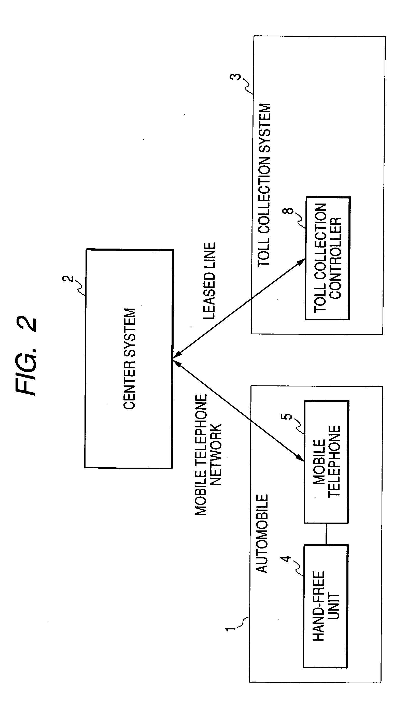
[0173] A communication payment system in the second embodiment realizes a toll payment in a road pricing system for charging a vehicle entering a specific region. FIG. 10 is a drawing to describe the concept of the road pricing system. As shown in the figure, if a toll collection area TA is set for a specific region, toll collection points TP . . . are provided at border points of the toll collection area TA on roads R . . . leading to the toll collection area TA. An automobile 1 entering the toll collection area TA from the outside of the toll collection area TA is charged.

[0174] (Configuration of Communication Payment System)

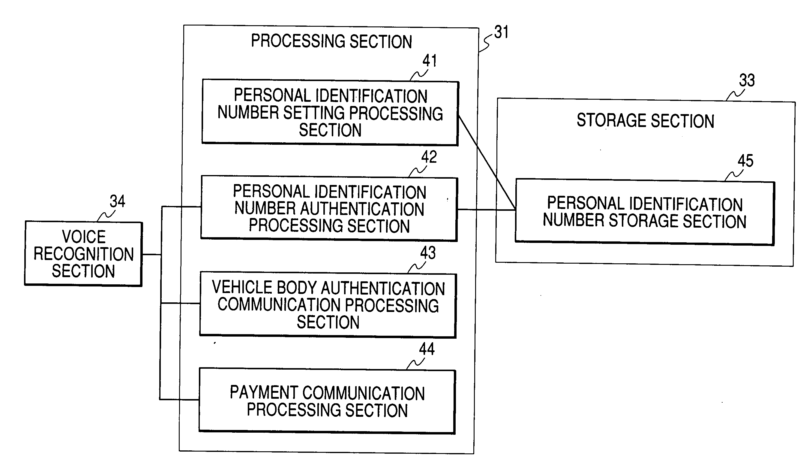
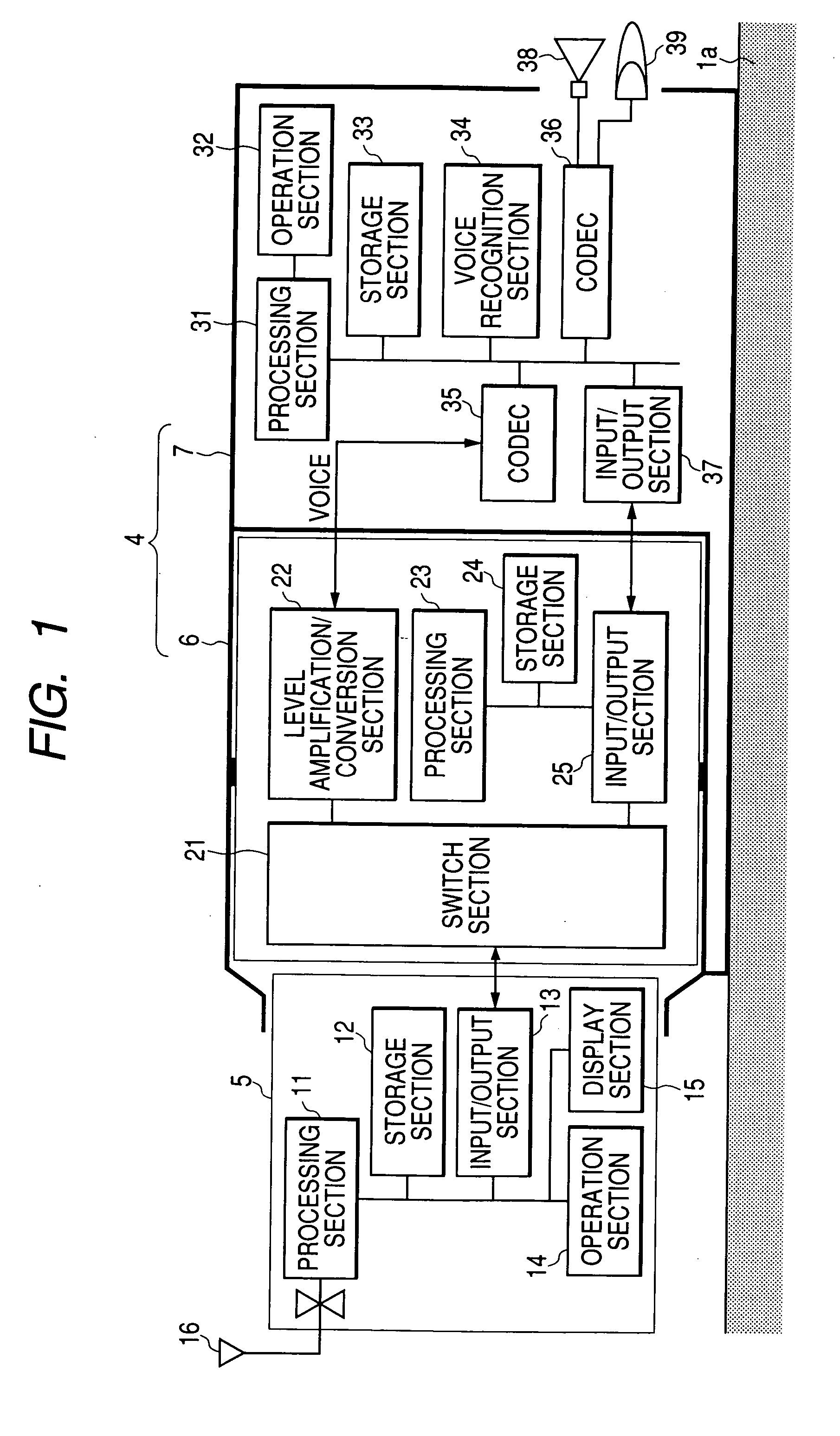
[0175] FIG. 11 is a block diagram to show t...

application example

[0212] (Application Example to Toll Collection Across Points)

[0213] Applying of the above-described communication payment system to a free-flow section toll collection system will be discussed with reference to FIG. 18. In this case, the number plate recognition unit 80 is installed ahead of a toll collection point B in the traveling direction of the automobile 1. First, when the automobile 1 enters a toll collection point A, the hand-free unit 4 is started as described above. At this point in time, point information A is stored in the storage section 33. Next, when the automobile 1 enters the toll collection point B, the hand-free unit 4 also transmits the point information A to the center system 2 in performing payment processing as described above, and the center system 2 considers the point information A to perform payment processing similar to that of the road pricing described above.

[0214] (Other Examples of User Identification System)

[0215] In the first and second embodiments...


PUM


Abstract

A mobile telephone 5 for conducting communications using a mobile telephone network is attached to a hand-free unit 4. A processing section 31 recognizes the personal identification number stored in a storage section 33 and the personal identification number voiced by a passenger by a voice recognition section 34, and collates the personal identification number with the personal identification number previously stored in the storage section 33 to perform authentication processing. If the passenger is authenticated, communications with a center system 2 are conducted through the mobile telephone 5, and payment processing is performed with the center system 2.

Description

[0001] 1. Field of the Invention[0002] This invention relates to a toll payment system making use of a communication terminal such as a mobile telephone in a telematic field.[0003] 2. Description of the Related Art[0004] In recent years, ETC (electronic toll collection) or an automatic toll collection system has been in practical use, and toll collection of toll roads, parking lots, etc., has been being developed to be an automation process. In Japan, to make the ETC practical, two-way communication, 5.8-GHz hand DSRC (Dedicated Short Range Communication) active system is adopted as a system for transferring information between a dedicated vehicle-installed terminal and a roadside machine. This system is also called transceiver system, wherein the dedicated vehicle-installed terminal also contains an oscillator and the dedicated vehicle-installed terminal and the roadside machine emit radio waves to each other on an equality with each other. Therefore, it is possible not only to tra...

Claims


Application Information

Patent Timeline
IPC IPC(8): G07B15/00G07B15/06G07F7/08G07F7/10G08G1/017G08G1/09H04M1/60
CPCG06Q20/14G06Q20/32G06Q20/341G06Q20/363G06Q20/4014G07B15/063G07F7/0866G07F7/0886G07F7/1008G07F17/0014H04M1/6075
Inventor KANAYAMA, KENJI
Owner ORMON CORP
Why Eureka
Try Eureka