Fluorescent polymer-QTL approach to biosensing

a polymer-qtl and biosensor technology, applied in the field of fluorescent biosensors, can solve the problems of important limitations and differentiations to fret relative to the polymer-qtl approach, cumbersome and time-consuming, and achieve the effect of enhancing the detection of target molecules

Inactive Publication Date: 2004-12-02
WHITTEN DAVID G +3
View PDF99 Cites 85 Cited by
  • Summary
  • Abstract
  • Description
  • Claims
  • Application Information

AI Technical Summary

Benefits of technology

[0017] It is an advantage of the present invention that target biological molecules can be detected at near single molecule levels.
[0018] It is a further feature of the invention that detection of target molecules may be enhanced by application of electric fields.
[0019] It is a further advantage of the present invention that it is simple and requires no elaborate preprocessing.
[0020] These and other objects are met by a composition of matter comprising: a) a fluorescent polymer, and b) a chemical moiety QTL comprising a recognition element, which binds to a target biological agent, and a property-altering element which alters fluorescence emitted by the fluorescent polymer when complexed together to a distinguishable degree, bound together by a tethering element, the chemical moiety being adapted for complexation with the fluorescent polymer. In the presence of binding of the recognition element to said target biological agent, the fluorescence emitted by the polymer is altered from that emitted when binding between said recognition element and said target biological agent does not occur.
[0021] FIG. 1 is a Stern-Volmer plot of fluorescence intensity of the polymer MPS--PPV in the presence of methyl viologen (MV.sup.2+).
[0022] FIG. 2 is a general illustration of the mechanism of the present invention.

Problems solved by technology

Despite its wide use, there are many disadvantages to ELISA.
For example, because the multi-step procedure requires both precise control over reagents and development time, it is time-consuming and prone to "false positives".
However, there are important limitations and differentiations to FRET relative to the polymer-QTL approach.
The ability to rapidly and accurately detect and quantify biologically relevant molecules with high sensitivity is a central issue for medical technology, national security, public safety, and civilian and military medical diagnostics.
However, they can be cumbersome and time-consuming, as discussed above.
The addition of an analyte containing a biological agent specific to the ligand removes the QTL molecule from the fluorescent polymer, which results in a "turning on" of the polymer fluorescence.
However, quenching occurs when the sample is treated with cAMP.
The very short excited state lifetime of J-aggregated cyanines (less than 50 ps) also limits the possibility that the excited dye aggregate can be quenched by dynamic interactions with potential quenchers not associating with the polymer in the ground state.
The failure to observe significant unquenching is attributed to the tendency of the 263 PRU cyanine polymer to associate strongly with neutral or charged biomacromolecules such as proteins and nucleic acids in aqueous solution.
Since electron transfer quenching is only effective through space over very short distances, the removal of the quencher away from the fluorescent polymer by only a few angstroms can result in an "unquenching" of the polymer fluorescence.
However, often times, the ligand and bioagent will be of comparable size such that the resulting steric effect on binding of the ligand to the bioagent is not sufficient enough to result in the breaking of the polymer-QTL association.
Thus, in the absence of an applied electric field, the addition of the bioagent will result in complex formation between the polymer-QTL and the bioagent (i.e., polymer-QTL:B).
Addition of the bioagent will result in complex formation but will not necessarily result in sufficient separation of the QTL:B complex from the polymer to "unquench" the polymer fluorescence.
Applying the field in sufficient strength will cause the charged QTL component to migrate with a consequent "unquenching" of the polymer fluorescence.
In cases where no "unquenching" occurs, application of an electric field (i.e., AC or DC) can result in unquenching either in the presence or absence of bioagent.

Method used


Image

  • Fluorescent polymer-QTL approach to biosensing
  • Fluorescent polymer-QTL approach to biosensing
  • Fluorescent polymer-QTL approach to biosensing

Examples


example 2

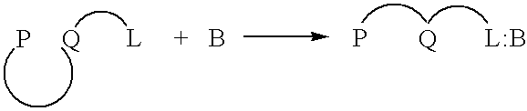
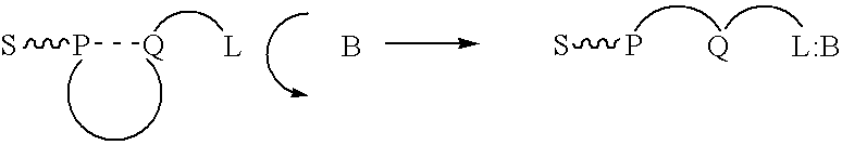
Anchored Polymer-tethered QTL Approach

[0107] In an aqueous solution, anionic polymer 1 illustrated in FIG. 11 is strongly quenched by cationic electron acceptors such as methyl viologen (Formula 3 illustrated in FIG. 11) or the viologen-biotin conjugate, Formula 4, shown in FIG. 11. (Chen, L.; McBranch. D. W.; Wang. H.-L.; Helgeson. R.; Wudl. F.; Whitten, D. G. Proc. Natl. Acad. Sci. 1999, 96, 12287-12292: Whitten. D.; Chen. L.; Jones. R.; Bergstedt, T.; Heeger. P.; and McBranch. D. in "Sensors and Optical Switches", Molecular and Supramolecular Photochemistry Vol. 7, Eds. K. S. Schanze and V. Ramamurthy, Marcel Dekker, Inc. Pub. In press).

[0108] As shown previously, the "unquenching" observed when the protein avidin is added to quenched solutions of polymer 1 complexed with QTL 4 provides a quantitative assay for the sensitive detection of a protein. Similarly, the cationic cyanine polymer 2 exhibits superquenching with the anionic anthraquinone disulfonate 5 and the corresponding ...


PUM

PropertyMeasurementUnit
molecular weight cutoffaaaaaaaaaa
Q-average sizeaaaaaaaaaa
fluorescentaaaaaaaaaa

Abstract

A chemical composition including a moiety comprising a quencher (Q), a tethering element (T), and a ligand (L) that associates with and quenches a fluorescent polymer is disclosed. When an analyte sample is introduced, the ligand (L) binds to a target biological agent if it is present, thereby causing the QTL molecule to separate from the fluorescent polymer resulting in an increase in detected fluorescence. The same chemistry is advantageously employed in a competitive assay. An electric field can also be applied to separate the QTL molecule from the fluorescent polymer. A method for detecting targets for these methods are also disclosed.

Description

[0001] This application claims priority from U.S. Provisional Application Ser. No. 60 / 202,647 filed May 8, 2000 and U.S. Provisional Application Ser. No. 60 / 226,902 filed Aug. 23, 2000. The entirety of those provisional applications are incorporated herein by reference.[0002] Field of the Invention[0003] The present invention relates to a fluorescent biosensor that functions by a novel Quencher-Tether-Ligand (QTL) mechanism. In particular, the polymer-QTL system provides for effective sensing of biological agents by observing fluorescence changes.DISCUSSION OF THE BACKGROUND[0004] The enzyme linked immunosorbant assay, ELISA, is the most widely used and accepted technique for identifying the presence and biological activity of a wide range of proteins, antibodies, cells, viruses, etc. It is a multi-step "sandwich assay" in which the analyte biomolecule is first bound to an antibody tethered to a surface. A second antibody then binds to the biomolecule. In some cases, the second anti...

Claims


Application Information

Patent Timeline
Patent Type & Authority Applications(United States)
IPC IPC(8): C12Q1/68G01N21/64G01N21/77G01N21/78G01N33/483G01N33/542G01N33/58
CPCG01N21/6428G01N33/542G01N33/582G01N2021/6432G01N2021/6439Y10S436/808C12Q1/68
Inventor WHITTEN, DAVID G.MCBRANCH, DUNCAN W.JONES, ROBERTBERGSTEDT, TROY S.
Owner WHITTEN DAVID G
Why Eureka
Try Eureka