
Apparatus and method for controlled application of reactive vapors to produce thin films and coatings

Inactive Publication Date: 2004-12-30
APPLIED MICROSTRUCTURES
View PDF27 Cites 71 Cited by
  • Summary
  • Abstract
  • Description
  • Claims
  • Application Information

AI Technical Summary

Benefits of technology

[0060] The resulting coated surface is typically very hydrophobic, as measured by water contact angle, which is typically about 103.degree. for DDMS films. The surface was particularly smooth, having an RMS of 0.2 nm, with no visible particulation or defects. The measured work of adhesion was reduced up to 3,000 times depending on the specific process / chemistry. Under the conditions provided above, the measured work of adhesion was reduced to about 30 .mu.J.sup.-2. The properties of the vapor deposited films are equivalent to or better than those reported for liquid-phase deposited films. In addition, use of vapor deposition prevents the stiction which frequently occurs during wet processing of the substrate.

Problems solved by technology

Historically, these types of coatings were deposited in the liquid phase, resulting in limited film property control and loss of device yield due to capillary forces.
The apparatus described for producing layers or coatings for use in electronic devices and / or micro-electromechanical systems devices enables application of the layers or coatings, but does not provide sufficient accuracy and repeatability in terms of the amount of the vaporous reactants provided to the substrate surface.
As a result, the precise composition of the layer or coating which is desired may not be available.
Further, the ability to reproduce the same coating reliably, time after time, is diminished due to lack of control over the precise amount of reactants supplied to the coating formation process.
This decreases the product yield and affects the commercial viability of a coating process.

Method used


Image

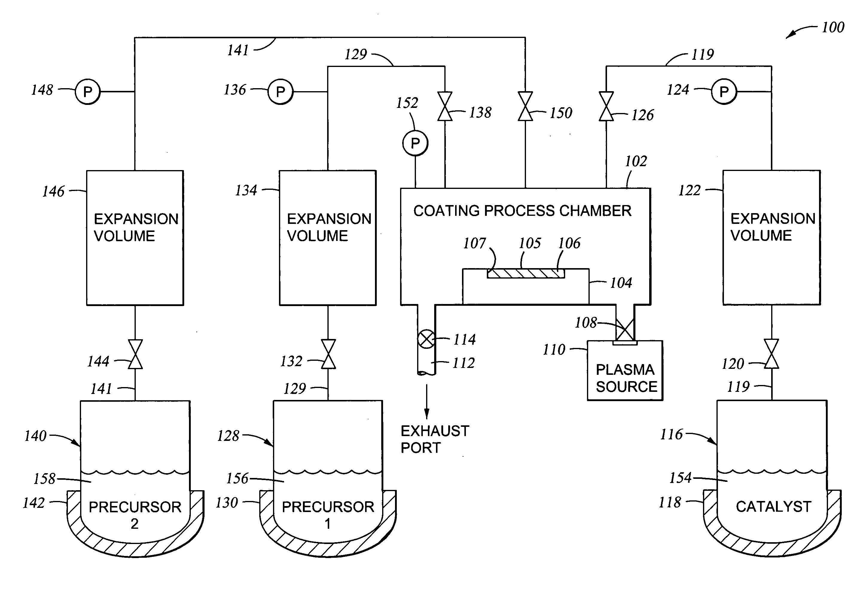
  • Apparatus and method for controlled application of reactive vapors to produce thin films and coatings
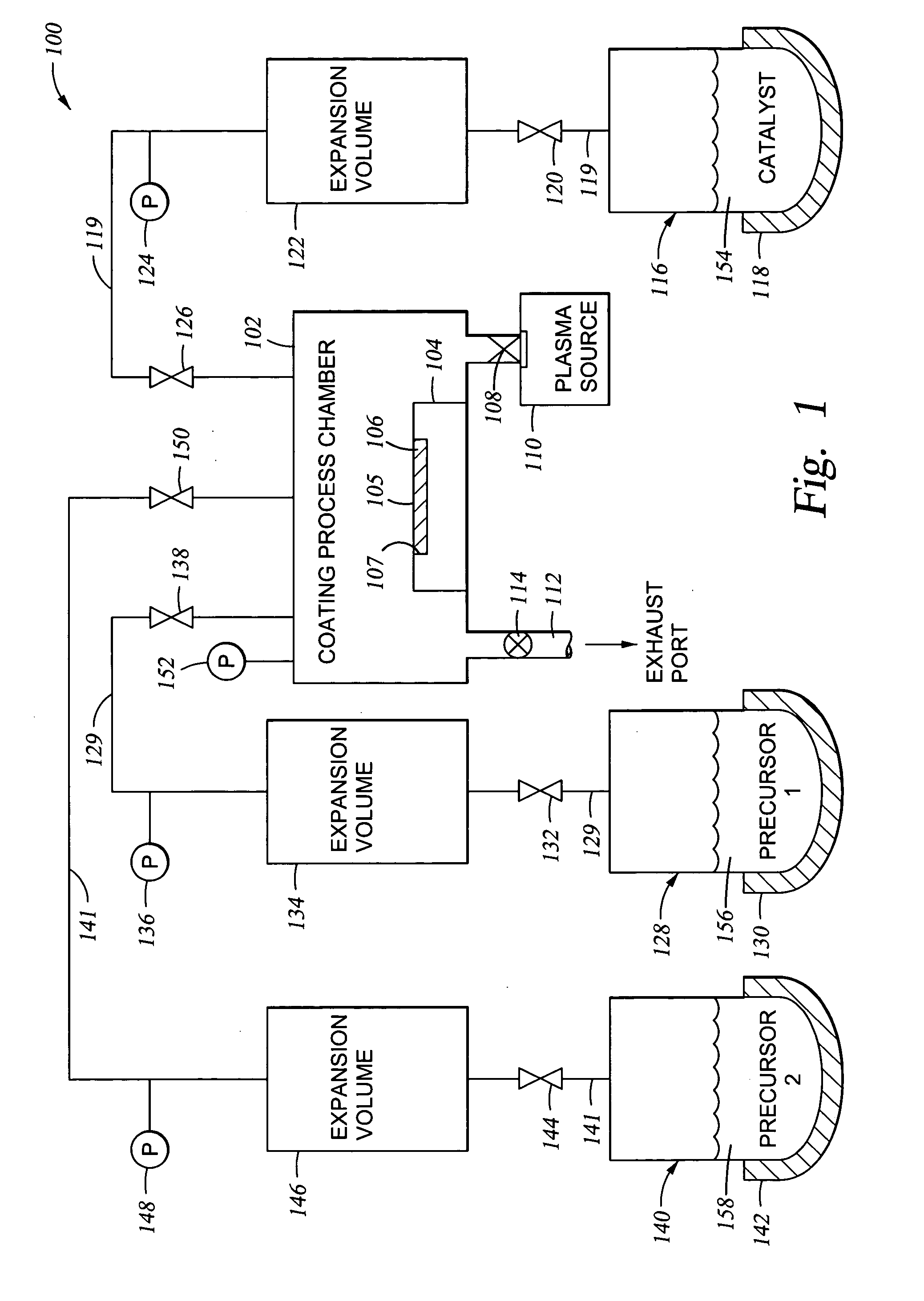
  • Apparatus and method for controlled application of reactive vapors to produce thin films and coatings
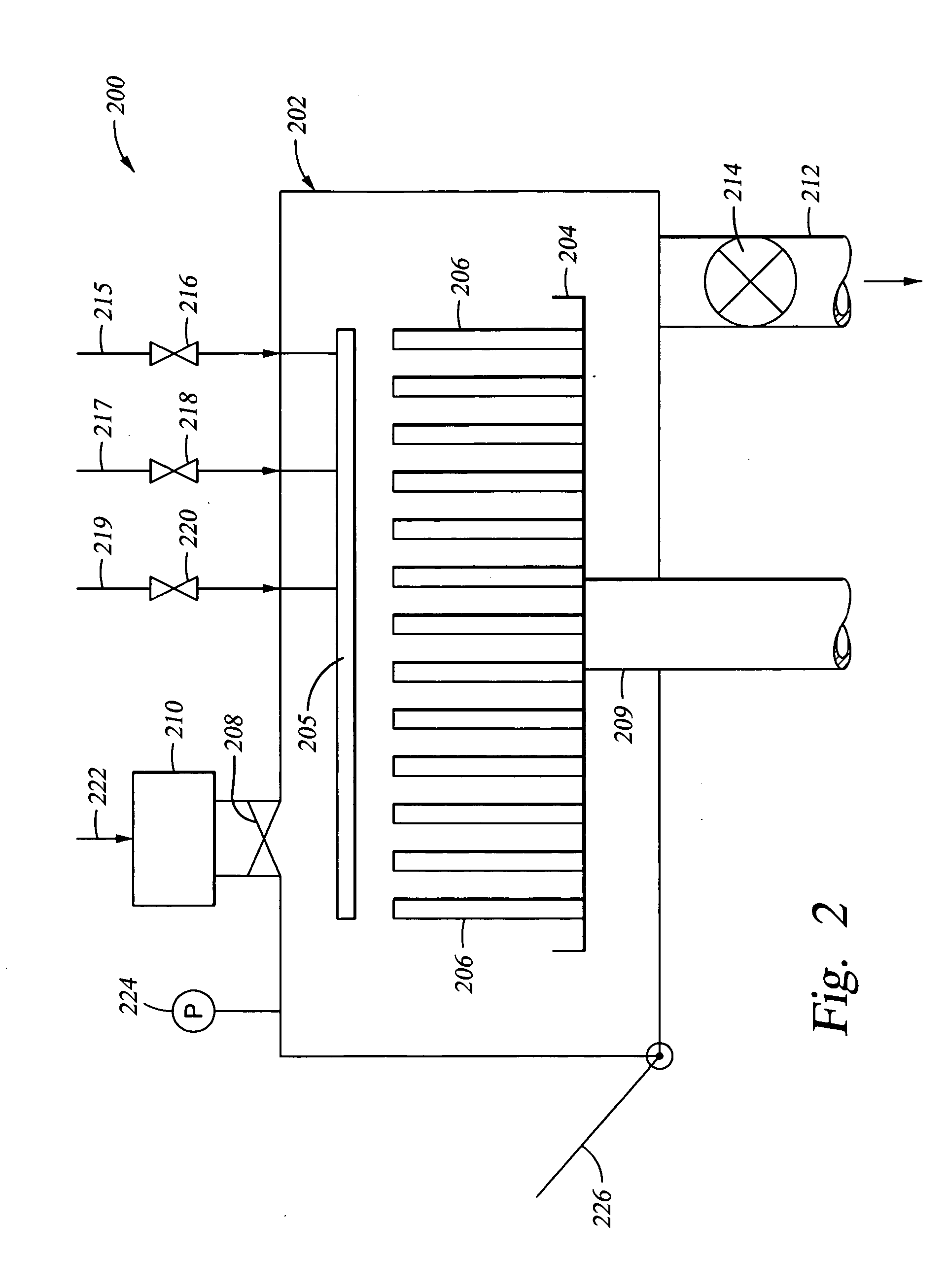
  • Apparatus and method for controlled application of reactive vapors to produce thin films and coatings

Examples


Embodiment Construction

[0025] As a preface to the detailed description, it should be noted that, as used in this specification and the appended claims, the singular forms "a", "an", and "the" include plural referents, unless the context clearly dictates otherwise.

[0026] We have developed an improved vapor-phase deposition method and apparatus for application of a thin (typically 5 .ANG. to 1,000 .ANG. thick, in and in some instances up to about 2, 000 .ANG. thick) film or coating to a semiconductor device substrate or a micro-electromechanical systems device. The method and apparatus are employed when at least one of the reactants or a catalyst used in coating formation must be vaporized prior to use, and where the amount of each reactant must be carefully controlled in terms of quantity available to react, in terms of time available for reaction at a given process pressure, or a combination of both. The method is particularly useful in the deposition of thin films or coatings where the thickness of the f...


PUM

PropertyMeasurementUnit
Angleaaaaaaaaaa
Vapor pressureaaaaaaaaaa
Temperatureaaaaaaaaaa

Abstract

A vapor phase deposition method and apparatus for the application of thin layers and coatings on substrates. The method and apparatus are useful in the fabrication of electronic devices, micro-electromechanical systems (MEMS), Bio-MEMS devices, micro and nano imprinting lithography, and microfluidic devices. The apparatus used to carry out the method provides for the addition of a precise amount of each of the reactants to be consumed in a single reaction step of the coating formation process. The apparatus provides for precise addition of quantities of different combinations of reactants during a single step or when there are a number of different individual steps in the coating formation process. The precise addition of each of the reactants in vapor form is metered into a predetermined set volume at a specified temperature to a specified pressure, to provide a highly accurate amount of reactant.

Description

[0001] This application is related to Provisional Application Ser. No. 60 / 482,861, filed Jun. 27, 2003 and entitled: "Method And Apparatus for Mono-Layer Coatings"; Provisional Application Ser. No. 60 / 506,846, filed Sep. 30, 2003, and entitled: ""Method Of Thin Film Deposition"; and, Provisional Application Ser. No. 60 / 482,861, filed Oct. 9, 2003, and entitled: "Method of Controlling Monolayer Film Properties".[0002] 1. Field of the Invention[0003] The present invention pertains to apparatus and a method useful in the deposition of a coating on a substrate, where the coating is formed from chemically reactive species present in a vapor which is reacted with the substrate surface.[0004] 2. Brief Description of the Background Art[0005] Both integrated circuit (IC) device fabrication and micro-electromechanical systems (MEMS) fabrication make use of layers or coatings of material which are deposited on a substrate for various purposes. In some instances, the layers are deposited on a s...

Claims


Application Information

Patent Timeline
IPC IPC(8): B05D1/18B05D3/14B05D7/24C09D4/00C23C16/00C23C16/455H01L
CPCB05D1/185B05D1/60B05D3/142B82Y30/00B82Y40/00C09D4/00C23C16/4485C08G77/04
Inventor KOBRIN, BORISNOWAK, ROMUALDYI, RICHARD C.CHINN, JEFFREY D.
Owner APPLIED MICROSTRUCTURES
Learn More