Exhaust emission control device for an internal combustion engine

an emission control device and internal combustion engine technology, applied in machines/engines, mechanical equipment, separation processes, etc., can solve the problems of reducing affecting the efficiency of so as to achieve the effect of simple and inexpensive configuration and efficient regenerating a particulate filter

Inactive Publication Date: 2005-01-06
MITSUBISHI FUSO TRUCK AND BUS CORPORATION
View PDF11 Cites 43 Cited by
  • Summary
  • Abstract
  • Description
  • Claims
  • Application Information

AI Technical Summary

Benefits of technology

[0010] The present invention has been made to solve the above problems, and an object thereof consists in providing an exhaust emission control device for an internal combustion engine, which is capable of efficiently regenerating a particulate filter in spite of a simple and inexpensive configuration thereof.

Problems solved by technology

Even with the continuous regeneration-type DPF, if the engine temperature is low, or the like, the PM trapped in the DPF cannot be completely eliminated depending on the operating conditions, resulting in the accumulation of the PM.
Consequently, while this method has an easy and inexpensive configuration, there is a problem that there generates unevenness in the PM combustion and that the PM in the outer circumferential portion of the DPF cannot be satisfactorily eliminated.
Moreover, in this case where the DPF is directly exposed to flame, there is great fear that the DPF is liable to be melted and damaged by being overheated.
Therefore, heat loss is great for raising the temperature of the DPF.
If the temperature rise of the DPF is prioritized, it creates a problem that the engine is applied with unnecessary heat load since the temperature of the cooling water is increased too much during the summer season, and the like, in which the outside air temperature is high.
Moreover, the combustion heater is provided with a vaporizing glow plug besides an ignition glow plug to vaporize fuel by carrying electricity to the vaporizing glow plug during a non-operation period of the combustion heater, which complicates the device and greatly deteriorates the energy efficiency.

Method used


Image

  • Exhaust emission control device for an internal combustion engine
  • Exhaust emission control device for an internal combustion engine
  • Exhaust emission control device for an internal combustion engine

Examples


Embodiment Construction

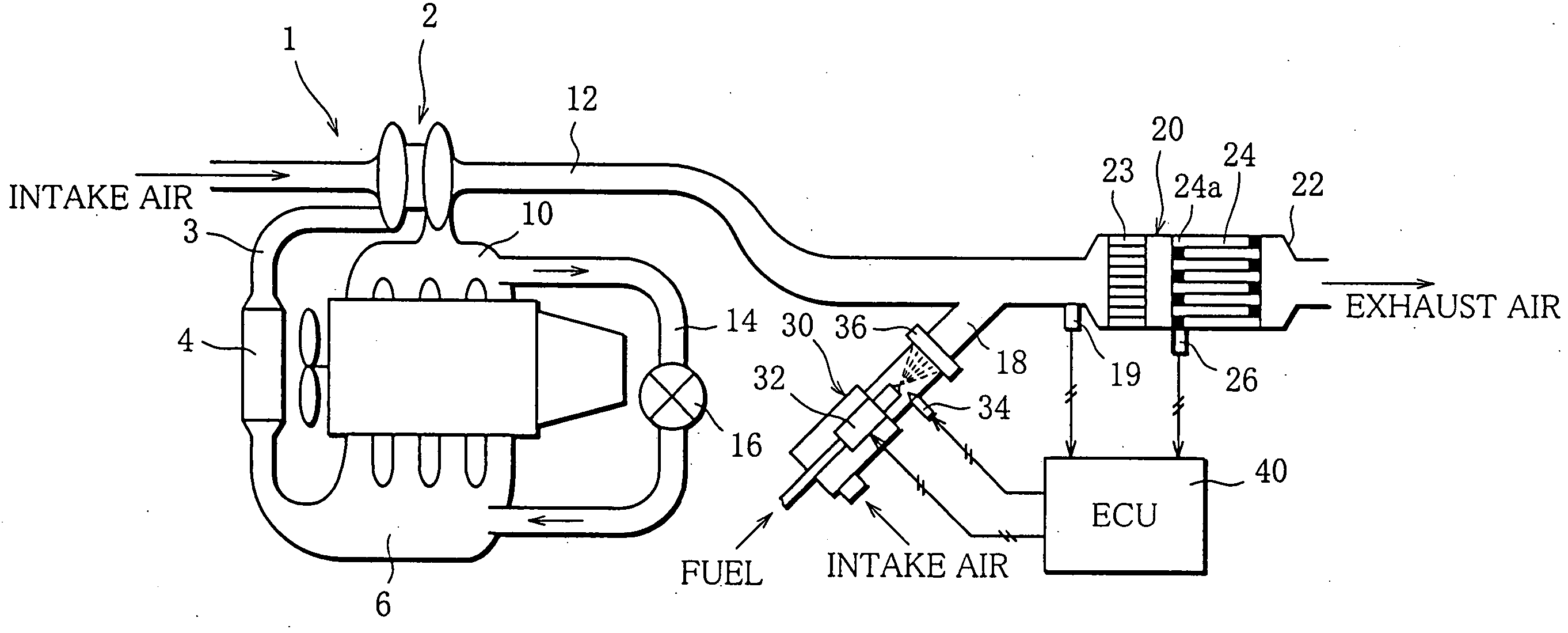
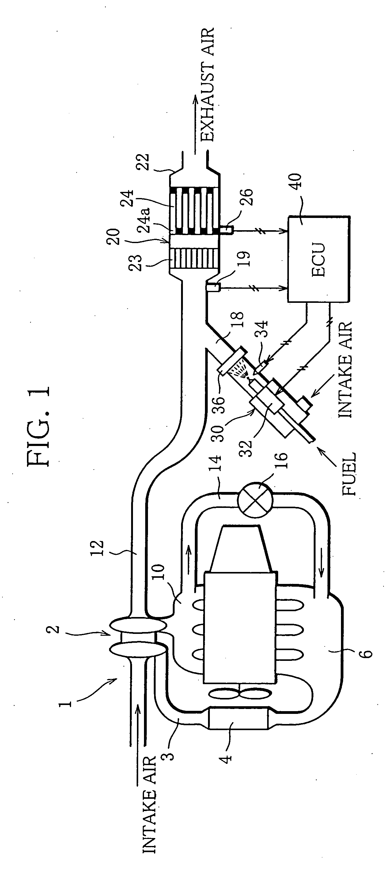
[0021]FIG. 1 schematically shows an exhaust emission control device for an internal combustion engine according to the present invention.

[0022] An engine 1 is for example a diesel engine and has a cylinder layout of an in-line four-cylinder type. There is mounted a turbocharger 2 in an intake passage 3 of the engine 1. Intake air supercharged by the turbocharger 2 flows into an intake manifold 6 through an inter cooler 4.

[0023] A fuel supply system of the engine 1 is constructed from a common rail system, for example. Although not shown, the system includes a common rail and an injector for each cylinder. As the common rail system is known, the detailed description of configuration of the common rail system will be omitted.

[0024] Exhaust ports for respective cylinders in the engine 1 are collected into one pipe by an exhaust manifold 10 and connected to an exhaust pipe 12. There is provided an EGR passage 14 between the exhaust manifold 10 and the intake manifold 6. An EGR valve ...


PUM

PropertyMeasurementUnit
timeaaaaaaaaaa
timeaaaaaaaaaa
temperatureaaaaaaaaaa

Abstract

A forced regeneration device which performs regeneration of a particulate filter includes oxidation catalysts (23, 24a) disposed upstream from the particulate filter or in said particulate filter and a burner (30) located upstream from the oxidation catalysts and operable switching between a combustion mode for combusting a fuel spray by inflammation to raise temperature of exhaust gases in an exhaust passage and a fuel supply mode for supplying only a fuel spray to the exhaust passage without inflammation. After the burner operates in the combustion mode, the burner operation is switched to the fuel supply mode.

Description

BACKGROUND OF THE INVENTION [0001] 1. Field of the Invention [0002] The present invention relates to an exhaust emission control device for an internal combustion engine, and more specifically to the technology of regenerating a particulate filter for capturing particulate matter contained in the exhaust gases. [0003] 2. Description of the Related Art [0004] The exhaust gases emitted from a diesel engine mounted on a bus, truck and the like, include a large quantity of minute particulate matter (hereinafter abbreviated as PM), besides HC, CO, NOx, etc. Therefore, as a postprocessing device of a diesel engine, a diesel particulate filter (hereinafter abbreviated as DPF ad libitum), which has a configuration in which after the PM is captured, the trapped PM is directly incinerated by an external heat source, such as a burner, has been developed and come into practical use. [0005] For instance, there is disclosed a device having a configuration in which a combustion heater is utilized ...

Claims


Application Information

Patent Timeline
Patent Type & Authority Applications(United States)
IPC IPC(8): F01N3/02F01N3/023F01N3/025F01N3/029F01N3/035F01N3/30F01N3/36F01N9/00F01N13/02F02B29/04F02B37/00F02M25/07
CPCF01N3/0231F01N3/025F01N3/0253F01N3/035F01N3/30F01N3/36F01N13/0097F01N2240/14F01N2250/02F02B29/0425F02B37/00F02M25/0707Y02T10/47F01N9/002F02M26/05Y02T10/40
Inventor TAKAHASHI, HIDEYUKIUMEZAWA, KATSUNORITSUTSUI, YASUHIRO
Owner MITSUBISHI FUSO TRUCK AND BUS CORPORATION
Why Eureka
Try Eureka