
Method for joining plastic structural component parts by means of laser radiation

a technology of laser radiation and structural components, applied in the direction of mechanical working/deformation, application, lamination, etc., can solve the problems of ever increasing occurrence of problems in joining and impaired surface quality on the side, and achieve the effect of preventing impairment of surface quality

Inactive Publication Date: 2005-01-06
JENOPTIK AUTOMATISIERUNGSTECHN
View PDF4 Cites 6 Cited by
  • Summary
  • Abstract
  • Description
  • Claims
  • Application Information

AI Technical Summary

Benefits of technology

[0009] Therefore, it is the primary object of the invention to prevent impairment of the surface quality by the falling in of material of the quality surface in thin-walled plastic structural component parts when the latter are connected to another part.
[0011] As a result of the present invention, a weld connection is formed without impairment of the quality surface of the thin-walled plastic structural component part, since the time for producing the joint connection is shortened and the depth to which the heat conduction process penetrates into the material is reduced. This prevents thermal influencing of the entire material thickness which occurs in the known methods with thin-walled materials having a thickness of 1 mm to 2 mm.

Problems solved by technology

In the supplier industry above all, this leads to an ever increasing occurrence of problems in joining because reinforcement elements or holding elements must be connected to thin-walled thermoplastic parts and a high surface quality must often be ensured.
In spite of the small penetration depth of the laser radiation, which is typically between 0.01 mm and 0.2 mm depending on material, it has been shown that with thin-walled plastic structural component parts with a material thickness of less than 2 mm there is a thermal influence on the material thickness throughout and the surface quality is impaired on the side with the quality surface due to the falling in of material.

Method used


Image

  • Method for joining plastic structural component parts by means of laser radiation
  • Method for joining plastic structural component parts by means of laser radiation

Examples


Embodiment Construction

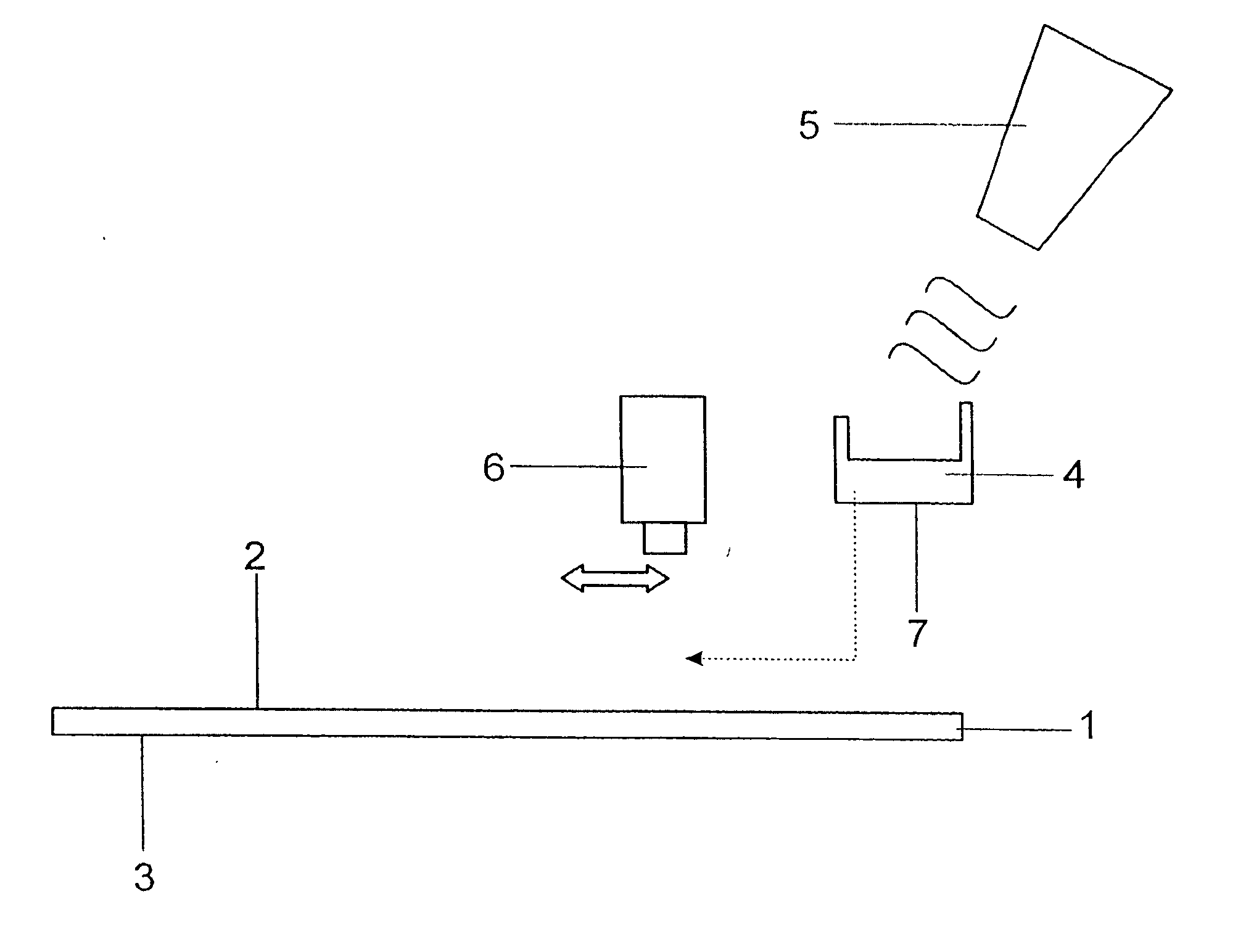
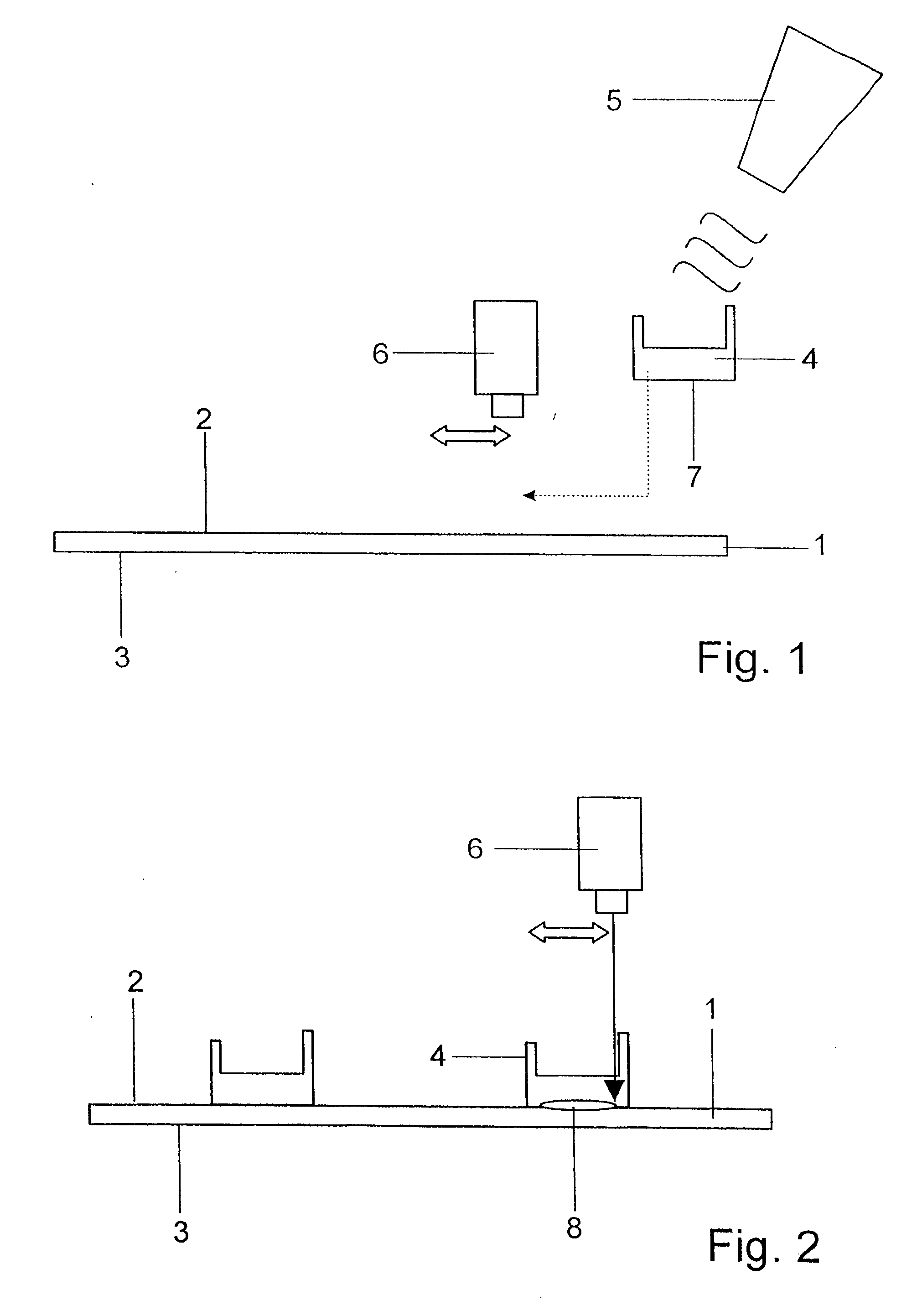
[0020] One of the plastic structural component parts shown in FIG. 1 is a thin-walled injection-molded part 1 having a quality surface 3 opposite from a joint surface 2 and is fabricated from a polymer material which absorbs a laser beam used in the transmission method of laser welding. The other plastic structural component part 4 which is preferably made from the same polymer as the injection-molded part 1 is heated to a temperature of about 50° C. below its melting point by means of a heat radiator 5 and is then placed in the position required for joining with the injection molded part 1.

[0021] The two plastic structural component parts 1 and 4 are fixed relative to one another by a mechanical holding device, not shown, and are welded together accompanied by the action of laser radiation from a laser radiation source 6 which can be constructed, e.g., as a high-power diode laser. The dimension of the gap between the joint surface 2 and a joint surface 7 of the plastic structural ...


PUM

PropertyMeasurementUnit
wavelength rangeaaaaaaaaaa
thicknessaaaaaaaaaa
thicknessaaaaaaaaaa

Abstract

In a method for joining plastic structural component parts by laser radiation, it is the object of the invention to prevent impairment of the surface quality by the falling in of material of the quality surface in thin-walled plastic structural component parts when the latter are connected to another part. A first thin-walled plastic structural component part having a quality surface is formed so as to be absorbent for the laser radiation and is welded by the transmission radiation method on a side located opposite from the quality surface to a second plastic structural component part which is transparent to the laser radiation. The transparent plastic structural component part is heated beforehand in order to reduce the temperature gradient between the plastic structural component parts when joining, so that a faster melting of the transparent plastic structural component part is carried out by heat conduction during joining, and a thermal expansion in the absorbing plastic structural component part in the direction of the quality surface is limited.

Description

CROSS-REFERENCE TO RELATED APPLICATIONS [0001] This application claims priority of German Application No. 102 32 727.0, filed Jul. 16, 2002, the complete disclosure of which is hereby incorporated by reference. BACKGROUND OF THE INVENTION [0002] a) Field of the Invention [0003] The invention is directed to a method for joining plastic structural component parts by means of laser radiation, in which a first thin-walled plastic structural component part having a quality surface is formed so as to be absorbent for the laser radiation and is welded by the transmission radiation method to a second plastic structural component part which is transparent to the laser radiation on a side located opposite from the quality surface. [0004] b) Description of the Related Art [0005] Automobile body parts are increasingly design elements which are formed as plastic covers to ensure a high surface quality and are constructed with very thin walls in order to economize on materials and reduce weight. ...

Claims


Application Information

Patent Timeline
Patent Type & Authority Applications(United States)
IPC IPC(8): B29C65/00B29C65/16B60R13/04
CPCB29C65/1616B29C65/1635B29C66/7352B60R13/04B29C66/0242B29C65/1654B29C66/91935B29C66/472B29C66/474B29C66/836B29C66/91411B29C66/91645B29C65/1674B29C66/1122B29C66/7392B29C66/73921B29K2995/0027
Inventor ZUEHLKE, HANS-ULRICHEBERHARDT, GABRIELEPREUSS, NORBERT
Owner JENOPTIK AUTOMATISIERUNGSTECHN
Learn More