Diagnostic imaging apparatus

a diagnostic imaging and apparatus technology, applied in the field of diagnostic imaging apparatus, can solve the problems of inaccurate understanding of the inside condition of the surface, inability to and inability to accurately diagnose the dental caries or the attached dental calculus, etc., to achieve accurate diagnostic image information, avoid the adverse effect of disturbance light, and diagnose the primary dental caries

Inactive Publication Date: 2005-01-06
MORITA MFG CO LTD
View PDF14 Cites 223 Cited by
  • Summary
  • Abstract
  • Description
  • Claims
  • Application Information

AI Technical Summary

Benefits of technology

[0021] The forth object of the present invention is to provide a light shielding hood for preventing outside light from entering at a light entrance for going out the radiation light and for entering the light from the diagnostic object at the forward portion, thereby avoiding the affect of the disturbance light such as interior illumination and sunbeam and making clear the diagnostic image information taken by the imaging means. More specifically, by providing the light shielding hood so as to be adjacent to the diagnostic object or so as to fix up the diagnostic object, the adverse effect of disturbance light is avoided and

Problems solved by technology

However, such an intraoral photography apparatus can only photograph under the condition where the surface of the tooth or the oral cavity is irradiated with visible light (wavelength of 380-760 nm) so that inside condition of the surface, dental caries or attached dental calculus haven't been accurately understood.
Therefore, in has been required to execute radiography in the prior art in order to know dental caries, deficit part, crack or attached dental calculus of biopsy such as invisible tooth, thereby causing a fear of X-ray exposure.
However, the apparatus has the following problems.
However, detection information when exciting light with specific wavelength is irradiated is only obtained so that dental caries condition can't be understood, therefore such information i

Method used


Image

  • Diagnostic imaging apparatus
  • Diagnostic imaging apparatus
  • Diagnostic imaging apparatus

Examples


embodiment 2

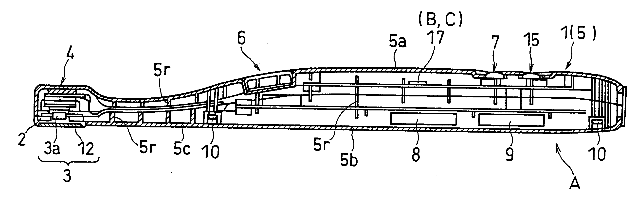
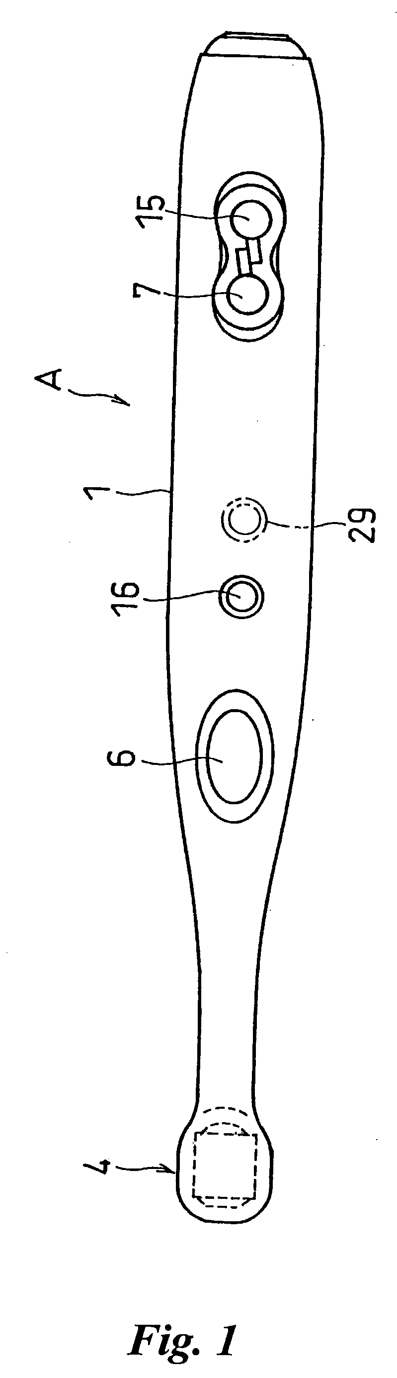
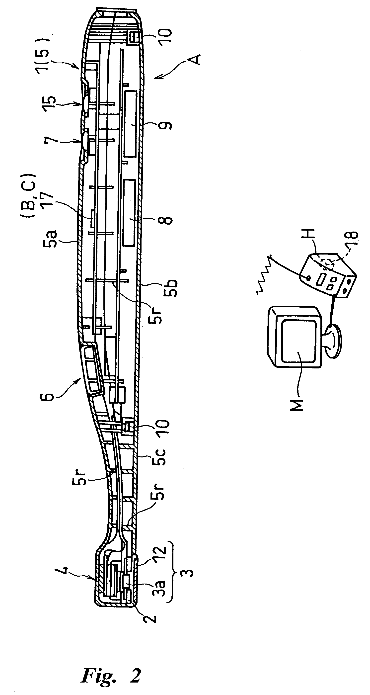
[0122]FIG. 13 shows one embodiment of a radiation source selection means D (corresponding to the light source selection switch 7 in FIG. 1). The radiation source selection means D constitutes a luminous means 2 comprised of four kinds of light emitting members 2a-2d (plural light emitting members radiating the light with different wavelength), that is, infrared ray, white light, ultraviolet ray 1 and ultraviolet ray 2, all of them are LEDs. Any one (or plural ones) of the plural light emitting means 2a-2d is (are) selectively driven. The radiation source selection means D is provided with four analog switches sw1-sw4 connected between a power source 8 and each light emitting member 2a-2d, four light source selection switches hs1-hs4, and a switch controller 19.

[0123] On operation of the first light source selection switch hs1 enables the first analog switch sw1 to be operated and to drive the infrared LED 2b. In the same manner, on operation of the second light source selection swi...

embodiment 3

[0124]FIG. 14 is one embodiment of the light receiving filter changing means. The filter changing means F in the figure is designed such that a support frame (filter unit) 24 provided with two light receiving filters 12, 12 with different cut-off wavelength range at both ends respectively is arranged so as to be freely rotated by hands around the center P of the axis parallel to the optical axis of the imaging means 3 (or luminous means 2). When the support frame 24 is rotated 180 angles around the axis center P, the light receiving filter 12 as shown in FIG. 14 is switched to another light receiving filter 12 (having different permeability).

[0125] The support frame 24 is constructed in a manner that a penetrating window 24a is formed between the axis center P and the light receiving filters 12, 12 respectively so as not to prevent the light from the luminous means 2 from transmitting. The support frame 24 may be rotated in the reverse direction as mentioned above or more than thre...

embodiment 4

[0126]FIG. 15 and FIG. 16 show another light receiving filter changing means. According to the filter changing means F in the figure, plural light receiving filters 12 are externally fitted up the forward portion 4 of the main body rotatably around the center Q of the axis in a direction perpendicular to the optical axis of the imaging means 3 or the luminous means 2. A square and tubular cover (filter unit) 25 comprised of a different light receiving filter 12 (with different permeability) at four faces, up, down, right and left is externally fitted up the forward portion 4 so as to be freely rotated. When the cover is rotated at 90 degrees, the light receiving filter 12 positioned directly under the CCD 3a can be switched to the next light receiving filter 12 apart from 90 degrees.

[0127] The cover 25 is formed like a hollow tube and is comprised of a cylinder 26 at both ends which is externally fitted up the cylindrical forward portion 4 so as to be freely rotated in its circumfe...


PUM


Abstract

A diagnostic imaging apparatus of hand piece type suitable for medical or dental use, comprising a main body held by operator's fingers, a luminous means for irradiating at least one of lights selected from excitation light, infrared light and ultraviolet light, and an imaging means provided in a forward portion of the main body. The imaging means comprises a solid-state image sensing device and an optical means for forming an optical image of a diagnosis object to be examined on the solid-state image sensing device and is so constructed as to output a predetermined diagnostic image information by receiving the light reflected from the diagnosis object and/or the fluorescence generated from the diagnosis object when irradiation of light from the luminous means to the diagnosis object is performed.

Description

DETAILED DESCRIPTION OF THE INVENTION [0001] 1. Field of the Invention [0002] The present invention relates to a diagnostic imaging apparatus for diagnosing dental caries, deficit tooth, crack of tooth, lesioned tooth, attachment of dental calculus or dental plaque, lesioned part of root canal, gum, bucca or tang in oral cavity, for diagnosing otolaryngology area, and for diagnosing rectum tumor. More specifically, the present invention relates to technology which can diagnose in an inner area of a diagnostic object, such as tooth, near the surface as well as on the surface. Further, the apparatus of the present invention isn't limited to an apparatus for doctors and it is preferably used as a diagnostic imaging apparatus for domestic use for confirming the appearance of tooth, dental caries, attached dental calculus or dental plaque. [0003] 2. Prior Art [0004] For example, a diagnostic imaging apparatus for diagnosing oral cavity is required to have compactly designed imaging means...

Claims


Application Information

Patent Timeline
IPC IPC(8): A61B1/24A61B1/247A61B5/00
CPCA61B1/00016A61B1/00089A61B1/00096A61B1/00101A61C19/004A61B1/0684A61B1/24A61B5/0088A61B1/0615A61B1/0676A61B1/0605G06F13/382G06F2213/0042
Inventor KATSUDA, NAOKIKINO, KENJIMATOBA, KAZUNARIIMAZATO, MINORU
Owner MORITA MFG CO LTD
Why Eureka
Try Eureka