
Gas treating device and gas treating method

a gas treatment device and gas treatment technology, applied in the direction of coatings, chemical vapor deposition coatings, metallic material coating processes, etc., can solve the problems of voids in holes to be embedded, severe design rules, and inability to cure films

Inactive Publication Date: 2005-01-06
TOKYO ELECTRON LTD
View PDF28 Cites 293 Cited by
  • Summary
  • Abstract
  • Description
  • Claims
  • Application Information

AI Technical Summary

Benefits of technology

[0022] According to the first aspect and the fourth aspect of the present invention, by discharging the processing gas through the first gas discharging part and further discharging the processing gas from the second gas discharging part, which is arranged around the first gas discharging part independently, into the periphery of the substrate to be processed, it is possible to prevent the concentration of the processing gas from being lowered in the periphery of the substrate to be processed, whereby an in-plane uniform gas processing can be applied to the substrate to be processed.
[0039] According to the tenth and the eleventh aspects, when alternately supplying the first processing gas and the second processing gas in order to form a film, the processing container is supplied with the first processing gas and the second processing gas through the gas supply pathways separated from each other in the gas discharging member. Therefore, in the gas discharging member, the first processing gas does not come into contact with the second processing gas, so that it becomes possible to prevent deposition of undesired film in the gas discharging member without any special cooling.

Problems solved by technology

Recently, however, both of miniaturization and high integration of a device have been particularly required and therefore, its design rule becomes severe in particular.
Correspondingly, as both device's line-width and diameter of holes become smaller with the progress of high aspect ratio, a “PVD” film has been getting incapacitated.
Then, there is a possibility that the “under” barrier layer is attacked by non-reacted WF6-gas, so that the barrier layer reacts with fluorine to expand its volume thereby producing a projecting defect called “volcano” and further, there is an occasion that voids occur in holes to be embedded.
However, in spite of the adoption of such a method, the step coverage of a nucleation film is deteriorated due to contamination etc. on the surface of a barrier layer as the under layer, so that the fill-in property of the main W-film gets worse.
However, this measure is believed to be insufficient.
Nevertheless, if the above technique is applied to a normal W-film deposition apparatus, then WF6-gas reacts to silane gas in a shower head as a gas discharging mechanism, so that a W-film is formed in the shower head, thereby decreasing the reproducibility among the surfaces of wafers.
In order to avoid an occurrence of such a problem, it is necessary to lower a temperature of a gas discharging part of the shower head less than 30° C. However, since the shower head is generally cooled down from its lateral surface, it is difficult to attain the temperature of a central part of the shower head less than 30° C. by means of generally cooling water.
In the present circumstances where the shower head is also large-sized because of large-sized wafers, the requirement of attaining the temperature of the central part of the shower head less than 30° C. would require an ultra cold chiller to cause a great increase in the installation cost of a system due to countermeasures of dew condensation etc.
However, due to the shower head being large-sized for large wafers that requires for the heater to have a high-power output, heat from the shower head to a container lid is also heat transferred, so that the heater is required to have more power to compensate such a dissipative heat.
The requirement makes it difficult to elevate the temperature of the shower head up to a predetermined temperature.
Additionally, with an apparatus being large-sized, if heating the shower head by the heater, then the shower head has a thermal expansion of the order of 1 mm, so that a problem of heat distortion about the shower head arises.

Method used


Image

  • Gas treating device and gas treating method
  • Gas treating device and gas treating method
  • Gas treating device and gas treating method

Examples


first embodiment

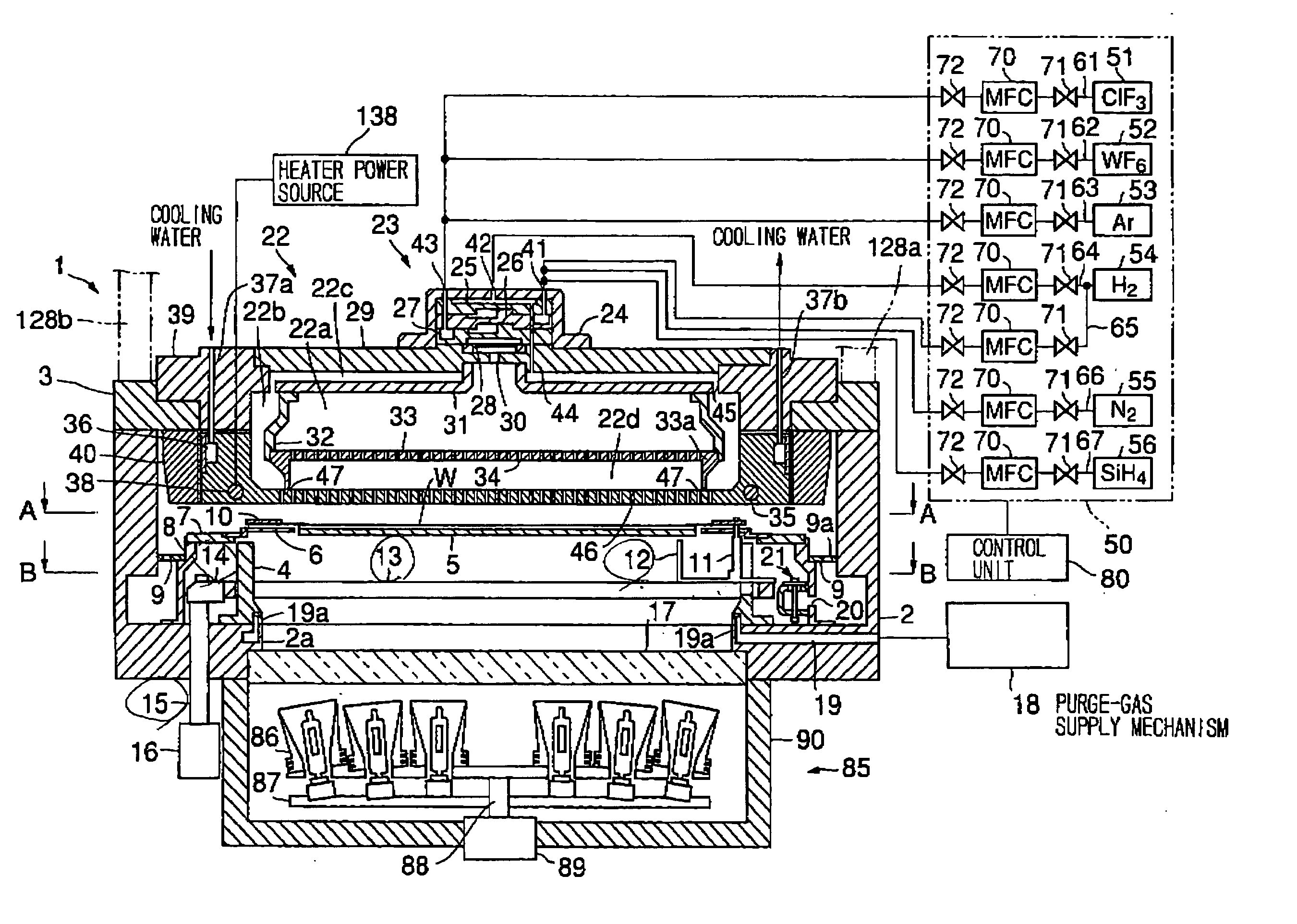
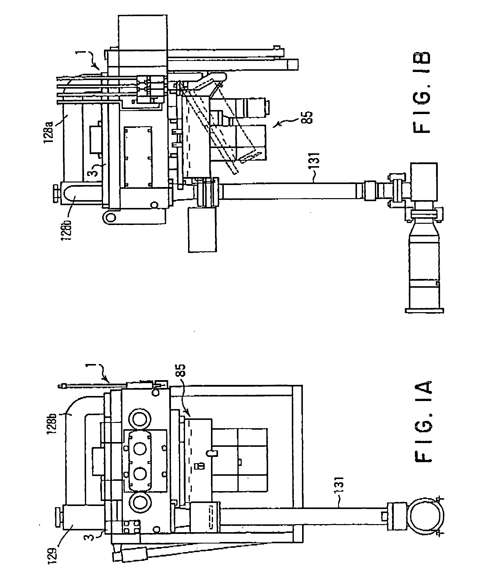
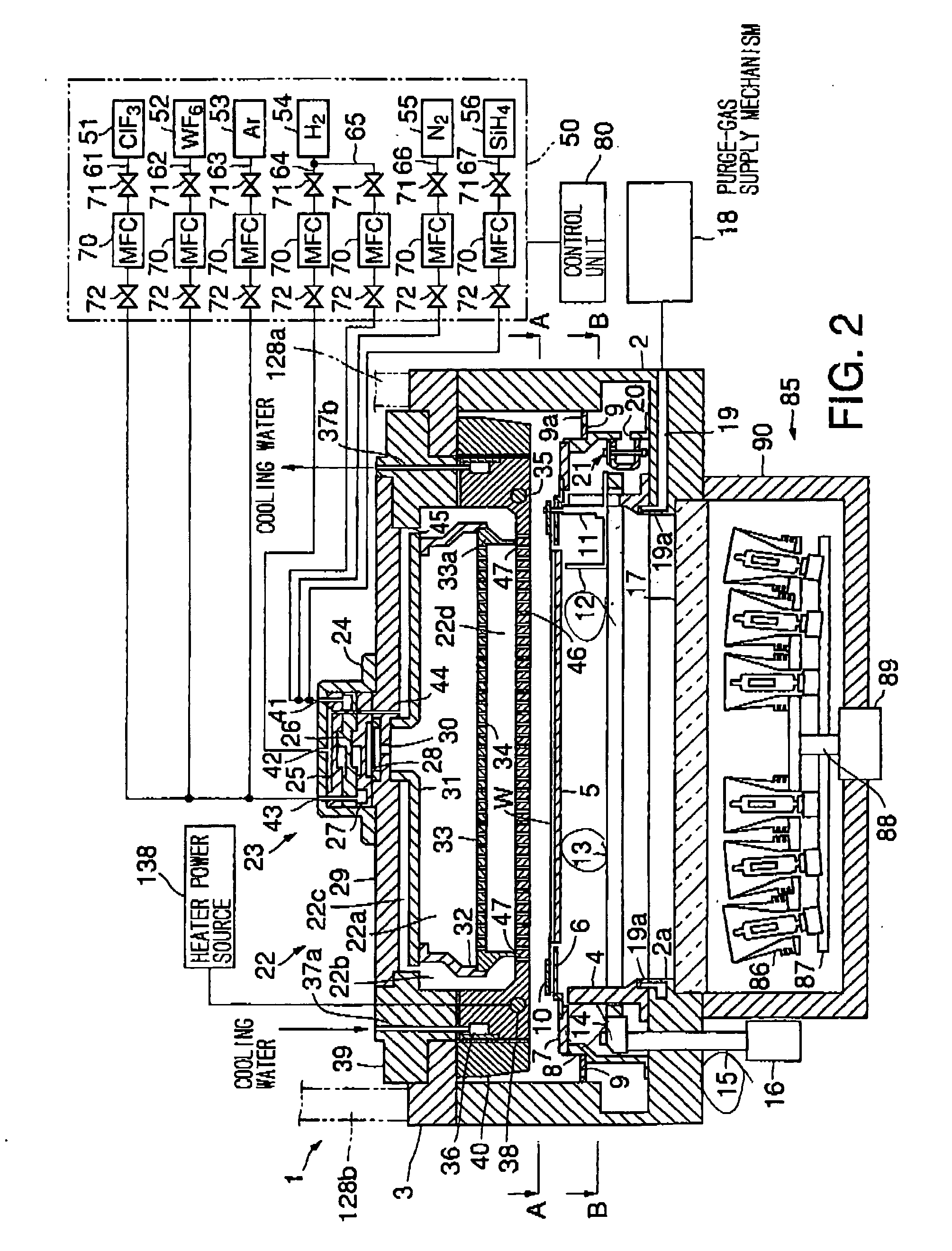
[0082]FIG. 1A is a front view of a CVD film deposition apparatus in accordance with the present invention. Further, FIG. 1B is a side view of the same apparatus. Still further, FIG. 2 is a schematic sectional view of the CVD film deposition apparatus, FIG. 3 a sectional view taken along a line A-A of FIG. 2, and FIG. 4 is a sectional view taken along a line B-B of FIG. 2. This CVD film deposition apparatus is provided to form a tungsten (W) film on a semiconductor wafer W (simply referred “wafer W” below) as a substrate to be processed, with the used of H2-gas and WF6-gas.

[0083] As shown in FIGS. 1A and 1B, this CVD film deposition apparatus has a main body 1. Under the main body 1, there is a lamp unit 85. On the top of the main body 1, a lid 3 supporting a shower head 22 described later is provided to be openable and closable. Further above the lid, upper exhaust pipes 128a, 128b are arranged so as to communicate with exhaust passages 121, 122 mentioned later, respectively. Again,...

second embodiment

[0140] Next, the present invention will be described.

[0141] In this embodiment, we explain an apparatus that embodies the above-mentioned technique (referred “Sequential Flow Deposition: SFD” below) of alternately performing a process of supplying SiH4-gas as the reduction gas and a process of supplying WF6-gas as the film deposition gas with the via of a purging process of evacuating while supplying an inert gas between the above processes, thereby forming an initial W-film on the surface of a wafer W.

[0142] As mentioned above, although the terminology “SFD” means a technique allowing a uniform nucleation film to be formed in even a minute device hole at high step coverage, the technique is by nature a technique of making the nucleation excellent. Therefore, the element W is easy to be formed on the surface of the shower head. Further, since the processing gas is consumed by the shower head, the water-to-water reproducibility is especially deteriorated and the film deposition rate...

third embodiment

[0166] Next, the present invention will be described.

[0167] This embodiment also relates to an apparatus for carrying out the technique “SFD” in the initial W-film forming process. In this embodiment, however, the supply pathway of SiH4-gas and WF6-gas in the initial W-film forming process is divided into respective pathways in order to suppress a reaction between these gases in the shower head.

[0168]FIG. 32 is a sectional view showing the main body of a CVD apparatus of this embodiment. Basically, this apparatus is constructed similarly to the CVD apparatus of FIG. 2 in the first embodiment and is different from it in its gas supply mechanism only. Therefore, elements identical to those of FIG. 2 are respectively indicated with the same reference numerals to simplify the explanation.

[0169] A gas supply mechanism 260 includes a ClF3-gas supply source 261 for supplying ClF3-gas as the cleaning gas, a WF6-gas supply source 262 for supplying WF6-gas being a W-containing gas as the de...


PUM

PropertyMeasurementUnit
sizeaaaaaaaaaa
thicknessaaaaaaaaaa
temperatureaaaaaaaaaa

Abstract

A gas processing apparatus 1 includes a processing container 2 for applying a processing to a wafer W while using a processing gas, a mount table 5 arranged in the processing container 2 to mount the wafer W, a shower head 22 arranged corresponding to the wafer W on the mount table 5 to discharge the processing gas into the processing container 2 and exhausting means 132 for exhausting the interior of the processing container 2. The shower head 22 has first gas discharging holes 46 arranged corresponding to the wafer W mounted on the mount table 5 and second gas discharging holes 47 arranged around the first gas discharging holes 46 independently to discharge the processing gas to the peripheral part of the wafer W. Thus, with a uniform gas supply to a substrate, it is possible to perform a uniform gas processing.

Description

TECHNICAL FIELD [0001] The present invention relates to a gas processing apparatus and a gas processing method for performing a gas processing of a substrate to be processed by use of a processing gas. BACKGROUND OF ART [0002] In the semiconductor manufacturing process, metal, for example, W (tungsten), WSi (tungsten silicide), Ti (titanium), TiN (titanium nitride), TiSi (titanium silicide), etc. or metallic compound thereof is deposited to form a film in order to fill up contact holes formed on a semiconductor wafer as an object to be processed (referred “wafer” hereinafter) or wiring holes for connecting wires to each other. [0003] As the film deposition for these elements, physical vapor deposition (PVD) technique has been employed conventionally. Recently, however, both of miniaturization and high integration of a device have been particularly required and therefore, its design rule becomes severe in particular. Correspondingly, as both device's line-width and diameter of holes ...

Claims


Application Information

Patent Timeline
Patent Type & Authority Applications(United States)
IPC IPC(8): C23C16/455C23C16/14C23C16/44H01L21/285H01L21/768
CPCC23C16/14C23C16/4411C23C16/4412C23C16/45519C23C16/45521C23C16/45523H01L21/76877C23C16/4557C23C16/45572H01L21/28562H01L21/76843H01L21/76876C23C16/45565
Inventor KASAI, SHIGERUYAMAMOTO, NORIHIKOTANAKA, MASAYUKI
Owner TOKYO ELECTRON LTD
Learn More