

Machining apparatus utilizing laser beam
a technology of laser beam and machining apparatus, which is applied in the direction of metal working apparatus, manufacturing tools, welding/soldering/cutting articles, etc., can solve the problem of forming the deterioration zone of the necessary thickness to break the wafer sufficiently precisely, and the relative long time taken to achieve the effect of forming the deterioration zone of the required thickness sufficiently efficiently
- Summary
- Abstract
- Description
- Claims
- Application Information
AI Technical Summary
Benefits of technology
Problems solved by technology
Method used
Image

Examples
first embodiment
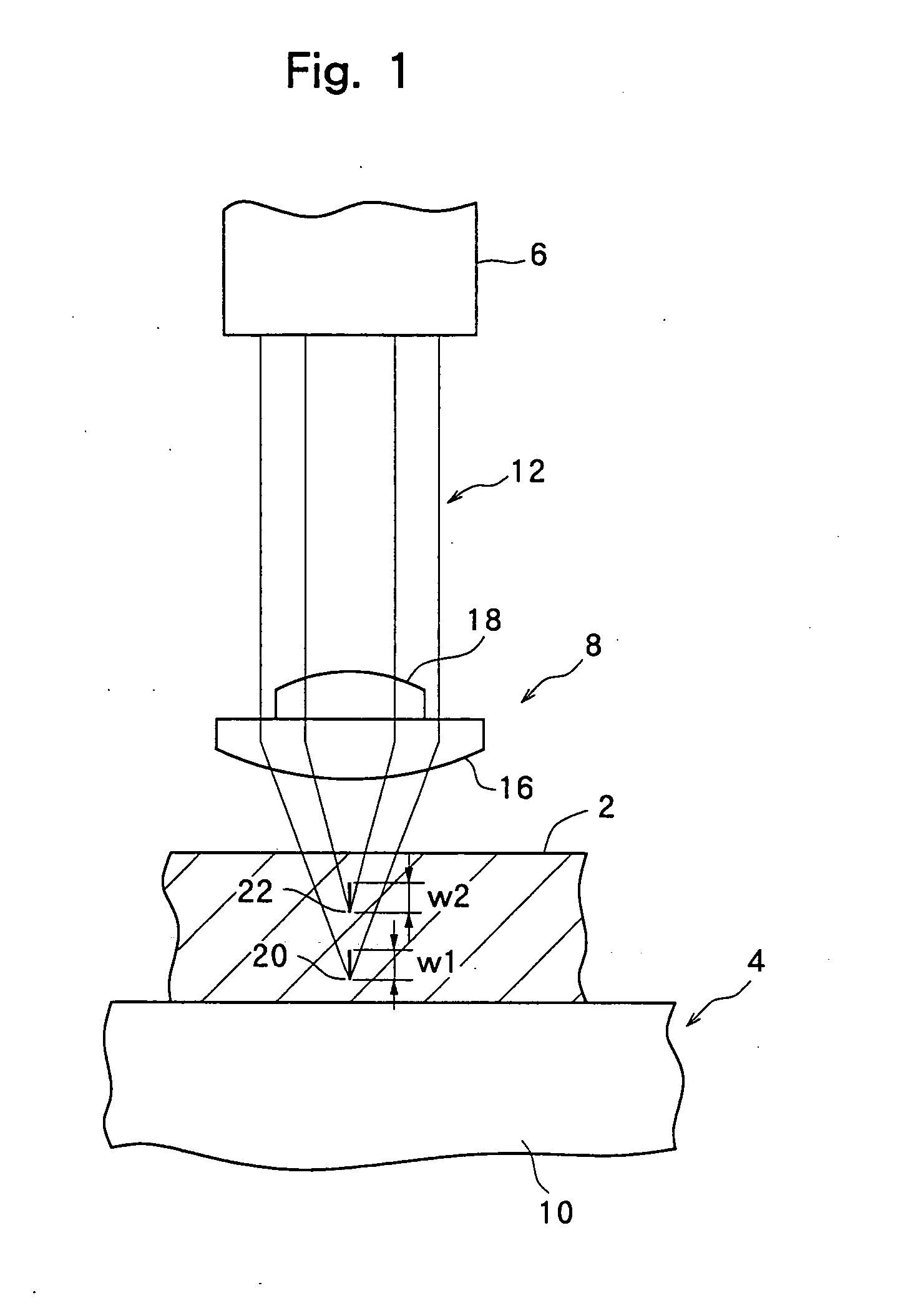
[0014]FIG. 1 schematically shows a machining apparatus constructed in accordance with the present invention. The illustrated machining apparatus comprises holding means 4 for holding a workpiece 2, laser beam generation means 6, and optical means 8.
[0015] The holding means 4 is composed of, for example, a holding member 10, which is a porous member or a member having a plurality of suction holes and / or suction grooves, and suction means (not shown) annexed to the holding member 10. The holding means 4 may be of a type attracting the workpiece 2, for example, a wafer, to the surface of the holding member 10 by suction.
[0016] It is important for the laser beam generation means 6 to be one generating a laser beam capable of passing through the workpiece 2. If the workpiece 2 is a wafer including a substrate, such as a silicon substrate, a sapphire substrate, a silicon carbide substrate, a lithium tantalate substrate, a glass substrate, or a quartz substrate, the laser beam generation ...
second embodiment
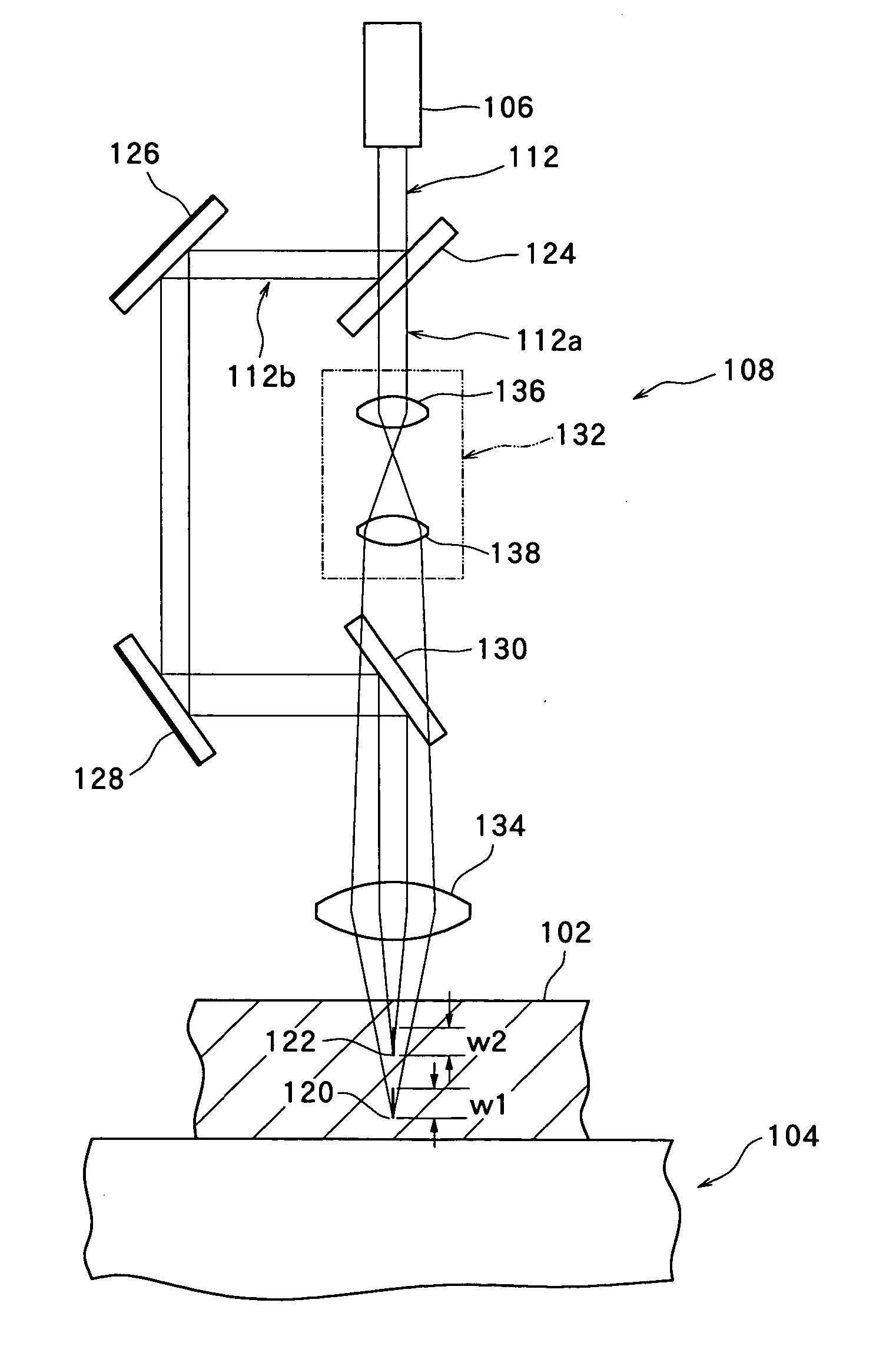
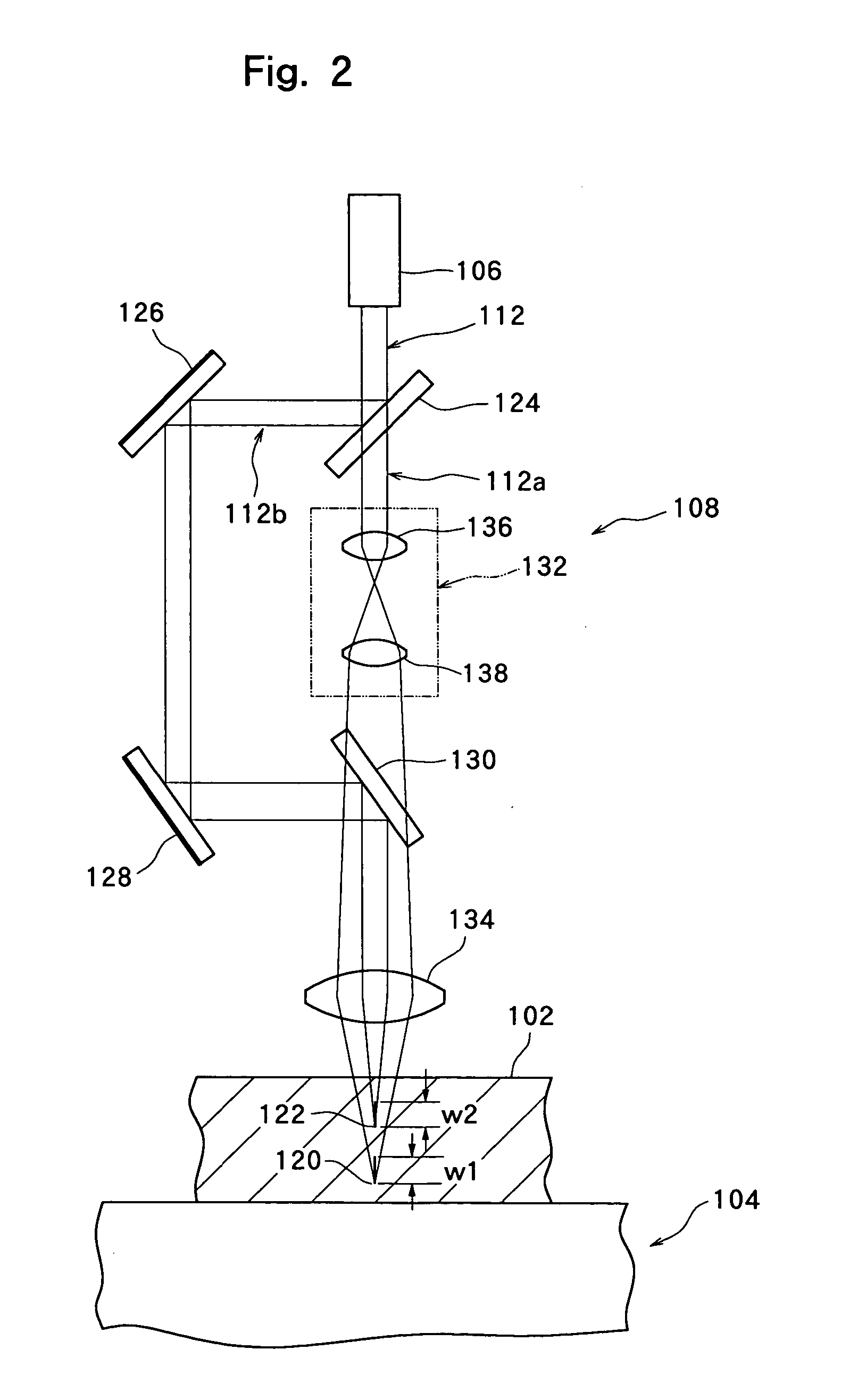
[0021]FIG. 2 shows a machining apparatus constructed in accordance with the present invention. The machining apparatus illustrated in FIG. 2 comprises holding means 104 for holding a workpiece 102, laser beam generation means 106, and optical means 108. The holding means 104 and the laser beam generation means 106 may be of the same configuration as the holding means 4 and the laser beam generation means 6 in the embodiment shown in FIG. 1.
[0022] The optical means 108 in the embodiment shown in FIG. 2 is composed of a half mirror 124 which functions as a splitter; a mirror 126; a mirror 128; a half mirror 130; an expander 132 which functions as diameter varying means; and a common focusing lens 134. The expander 132 includes two convex lenses 136 and 138. A laser beam 112 from the laser beam generation means 106 is separated into two laser beams, i.e., a first laser beam 112a which passes through the half mirror 124 and travels straight, and a second laser beam 112b which is reflect...
third embodiment
[0024]FIG. 3 shows a machining apparatus constructed in accordance with the present invention. The machining apparatus illustrated in FIG. 3 comprises holding means 204 for holding a workpiece 202, laser beam generation means 206, and optical means 208. The holding means 204 and the laser beam generation means 206 may be of the same configuration as the holding means 4 and the laser beam generation means 6 in the embodiment shown in FIG. 1.
[0025] The optical means 208 in the embodiment shown in FIG. 3 is composed of a half mirror 224 which functions as a first splitter; a half mirror 225 which functions as a second splitter; a mirror 226; a mirror 227; a mirror 228; a mirror 229; a half mirror 230; a half mirror 231; an expander 232 which functions as a first diameter varying means; an expander 233 which functions as a second diameter varying means; and a common focusing lens 234. The expander 232 includes two convex lenses 236 and 237. The expander 233 also includes two convex lens...
PUM
| Property | Measurement | Unit |
|---|---|---|
| wavelength | aaaaa | aaaaa |
| optical axis | aaaaa | aaaaa |
| diameters | aaaaa | aaaaa |
Abstract
Description
Claims
Application Information