
Method for assessment of the state of batteries in battery-supported power supply systems

a technology for power supply systems and batteries, applied in the direction of instruments, material analysis, transportation and packaging, etc., can solve the problems of affecting the life of batteries, and requiring a high degree of maintenance effort in the procedure, so as to shorten the life of batteries and promote li

Inactive Publication Date: 2005-01-13
SIEMENS AG
View PDF15 Cites 35 Cited by
  • Summary
  • Abstract
  • Description
  • Claims
  • Application Information

AI Technical Summary

Benefits of technology

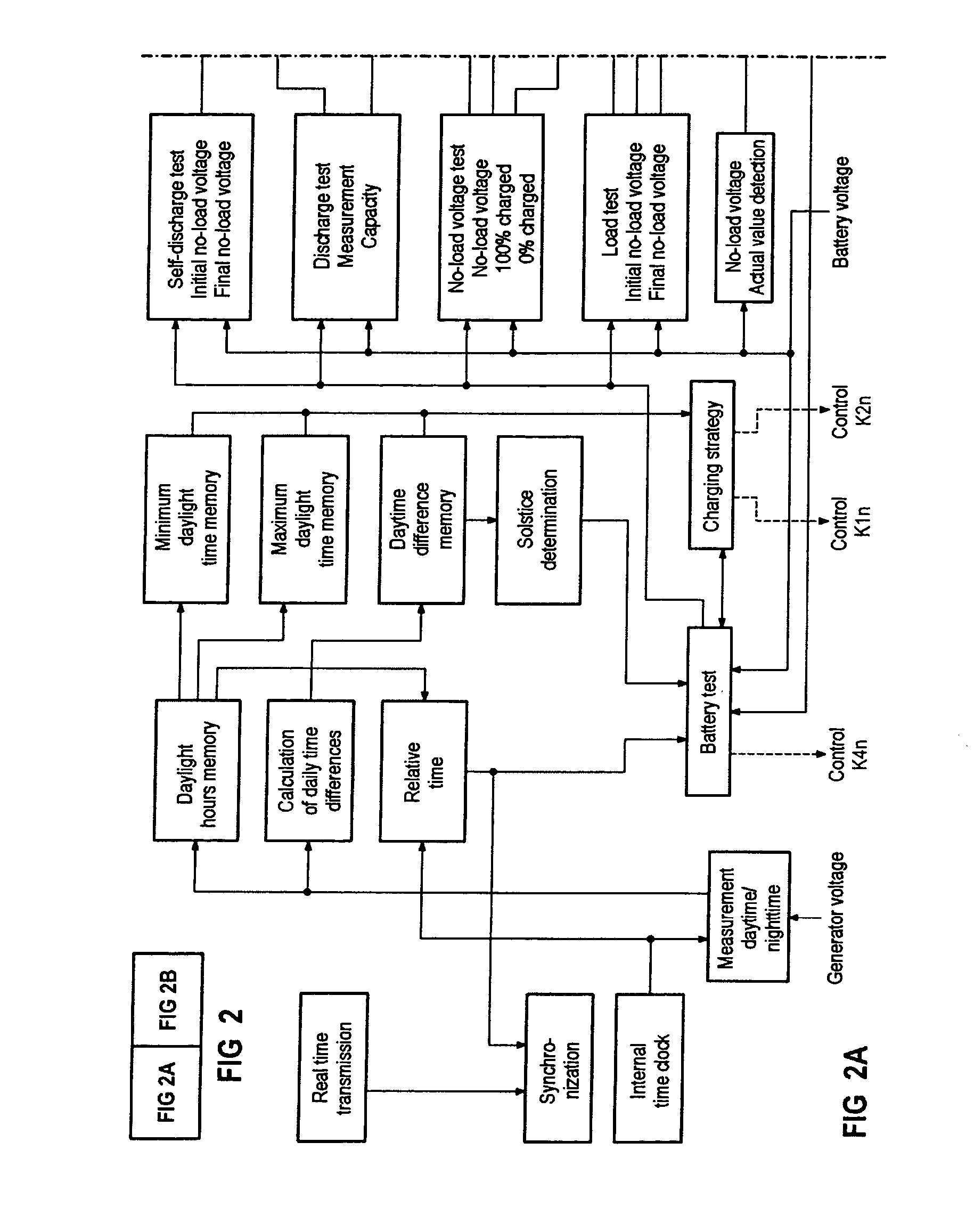
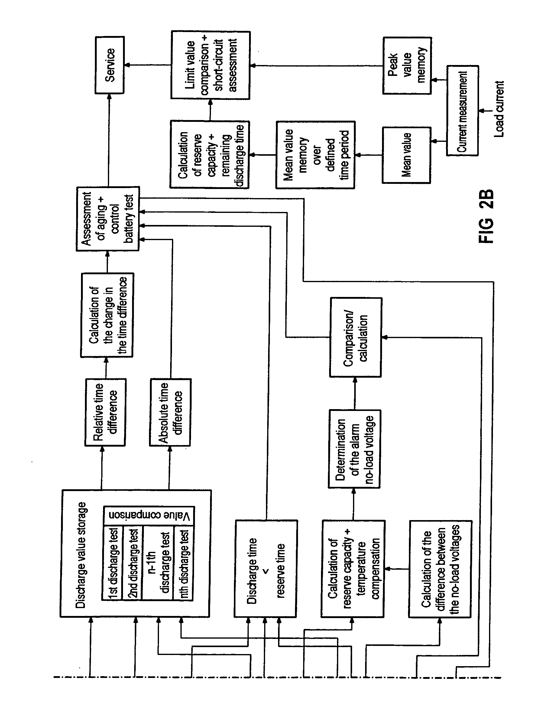
[0016] The change in the reduction of the discharge time between battery discharges may on the one hand be used to determine the aging progress while, on the other hand, the measurement system can also use this to determine the time window between two battery discharges. This method is preferred in order to avoid unnecessary stress conditions during the battery test in comparison to presetting constant time patterns for discharge processes.
[0020] The advantage of the method is that the state of a battery which has been disconnected from the power supply system can be tested by means of a simple voltage measurement and time control without any stringent accuracy requirements, and an analysis of its aging and life expectancy can be carried out by comparison with data from previous measurements stored in the measurement system. This avoids integration errors resulting from time-dependent measurement methods or recalibration procedures, so that fully automatic operation is feasible. Since relative variables are determined in all the analysis processes, there is no need to know the absolute capacity nor the type of battery. The behavior of the load is likewise not relevant, since the discharge test is always carried out on the same load, preferably with a constant current. In fact, it is sufficient to state the type of technology of the battery (lead-zinc, nickel-cadmium, lithium-ion battery, etc.). The system defines the final charge voltage and the final discharge voltage as well as the charging / discharge method on the basis of the battery voltage that is produced.
[0028] The third option is control of a pure standby mode. For this purpose, the generator and one battery path supply the load. The other battery paths remain charged and available. Furthermore, each path is recharged in order to compensate for the self-discharge by cyclic switching of the generator to another battery path in order to supply the load. Since this variation generally equalizes the daily energy balance, it is possible to assume that an energy store will be virtually completely charged. Although this state is the most desirable, the side effects of fully charged batteries, depending on the chemical type, must be borne in mind, since it is also possible to shorten their life.
[0033] The second derivative of a curve of the annual daylight hours is ideally used to determine the point of inflection in the rise. However, in the simplest case, it is sufficient to use the area of the daylight hours curve in which the difference between the daylight times is the same. Times in the period of the start of spring and autumn additionally generally provide a correction. The correction of an advantageous discharge time for battery tests should be before these points of inflection, so that the discharged battery is charged at the time of the start of spring, or else in particular at the start of autumn. Particularly in periods where the daylight hours are decreasing, the reduction in the solar radiation can unnecessarily lengthen the charging time and restrict the availability of charged energy stores.

Problems solved by technology

One major problem in battery-supported power supply systems is the assessment of the state of charge, of the aging and of the life expectancy of the energy store, irrespective of whether an energy store is used as an emergency battery, as a back-up battery or as a cyclically operated main battery.
This procedure requires a high degree of maintenance effort.
However, the major disadvantage of this method becomes evident in the case of autonomous systems operated in the island mode.
Even if the current detection measurement error is very small, this is integrated over time to produce a very major discrepancy from the actual values, so that the energy balance becomes highly erroneous and unusable for specific state analyses.
This problem is worse, in particular in power supplies which supply loads on an event-controlled basis, that is to say in systems in which only a small amount of power is intended to be provided over a specific time period for monitoring purposes, but greater amounts of power are provided for operation of loads when an event is triggered.
Furthermore, in the case of autonomous systems, it must always be assumed that the energy balance is not equalized over lengthy time periods.
However, the monitoring of the measurement system and the independence from the mains system for specific charging of the batteries involve a high degree of complexity.
These methods are relatively accurate provided that the battery is operated cyclically, but are subject to errors for battery states of charge above 80%, for small charging and discharge currents and when large temperature differences occur during operation.

Method used


Image

  • Method for assessment of the state of batteries in battery-supported power supply systems
  • Method for assessment of the state of batteries in battery-supported power supply systems
  • Method for assessment of the state of batteries in battery-supported power supply systems

Examples


Embodiment Construction

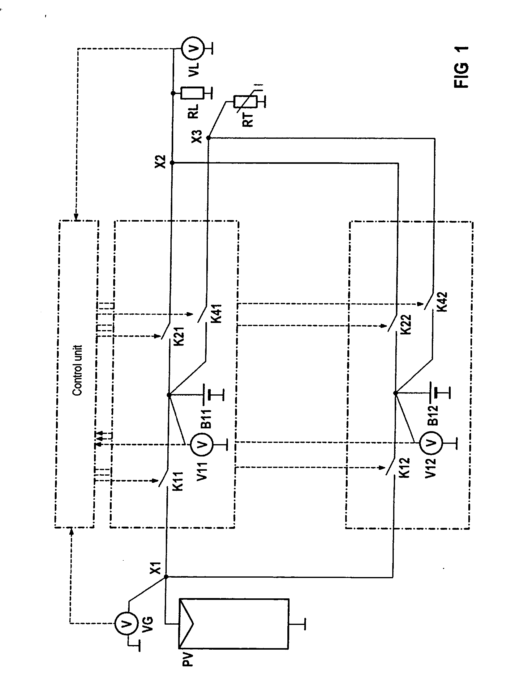
[0058] The exemplary embodiment relates to a power supply system having two parallel battery paths with the batteries B11 and B12, which are subjected to charging and discharge cycles in the long term and are recharged by a photovoltaic generator PV, with a respective voltage measurement device V11, V12 as well as a respective switch K21, K22 with a series-connected test resistor RT in each case being arranged parallel with each battery B11, B12. Each battery path has a respective generator switch K11, K12 and a respective load switch K41, K42 for connection to a load RL. At the generator end, the voltage can be determined by a voltage measurement device VG, and at the load end RL, it can be determined by a voltage measurement device VL.

[0059] According to the method, a test is carried out on the individual batteries B11, B12, or battery paths, removed from the power supply system. The method relates to an automated algorithm for determining parameters relating to the instantaneous...


PUM


Abstract

After disconnection from the power supply system, a discharge characteristic of the no-load voltage is recorded automatically by means of a control unit across a discharge resistance during a stage-by-stage discharge cycle from a charged battery which is being operated for the first time on the power supply system. This stage-by-stage discharge cycle is repeated at times which can be defined, in order to record an instantaneous discharge characteristic of the no-load voltage, and an alarm no-load voltage is determined from the instantaneous discharge characteristic of the no-load voltage from a previously defined reserve time and from the final discharge voltage as determined in the first measurement, which alarm no-load voltage represents a measure of the energy which in each case still remains in the battery, and on reaching which during operation on the load, an alarm is produced for the operator of the power supply system.

Description

CLAIM FOR PRIORITY [0001] This application claims the benefit of priority to U.S. Provisional Application No. 60 / 472,411, filed in the German language on May 22, 2003, the contents of which are hereby incorporated by reference.TECHNICAL FIELD OF THE INVENTION [0002] The invention relates to a method for assessment of the state of batteries in battery-supported power supply systems. BACKGROUND OF THE INVENTION [0003] One major problem in battery-supported power supply systems is the assessment of the state of charge, of the aging and of the life expectancy of the energy store, irrespective of whether an energy store is used as an emergency battery, as a back-up battery or as a cyclically operated main battery. The need for a valid statement about the storage state of a battery must be regarded as particularly strong when the battery-supported power supplies are used for feeding systems with enhanced safety, security or availability requirements. It is particularly important to determ...

Claims


Application Information

Patent Timeline
Patent Type & Authority Applications(United States)
IPC IPC(8): G01R31/36
CPCG01R31/3637G01R31/388
Inventor KOSTER, KAYWALTER, HARALD
Owner SIEMENS AG
Learn More