Lyophilic fuel cell component

a fuel cell and lyophilic technology, applied in the field of fuel cells, can solve the problems of restricting or blocking the flow of fuel into the cell, limiting the use of materials with such a high temperature process, and affecting so as to improve the lyophilicity of the exposed surface, facilitate mass production, and improve the effect of wettability

Inactive Publication Date: 2005-01-13
ENTEGRIS INC
View PDF23 Cites 47 Cited by
  • Summary
  • Abstract
  • Description
  • Claims
  • Application Information

AI Technical Summary

Benefits of technology

The present invention fulfills the need of the industry for an inexpensive, easily mass producible, polymeric fuel cell component having improved wettability. In an embodiment of the invention, a fuel cell component body is formed from polymer material. At least a portion of the surface of the component body is exposed to cold plasma to increase the lyophilicity of the exposed surface. The result is a fuel cell component with surfaces having improved lyophilicity so that liquid on the component adheres closely to the surface in relatively flat droplets or sheets. These surfaces may be selectively provided on critical areas of the component, such as for example on flow channel wall surfaces of bipolar plates and membrane electrode assemblies, thereby inhibiting liquid blocking of the flow channels during operation of the fuel cell.
In another embodiment of the invention, the component surfaces may be treated with ultraviolet light in the presence of ozone or oxygen to produce a surface with enhanced lyophilicity. In other embodiments of the invention, a thin layer of inherently hydrophilic polymer, such as polyvinyl alcohol, may be applied to the component surface to provide a lyophilic surface. The thin layer may be applied by plasma polymerization methods, film insert molding, compression molding or any other suitable method.

Problems solved by technology

A persistent challenge in the design of fuel cells is that of managing water and other liquids in the cell.
This water is generally produced on the cathode side of the cell, and if allowed to accumulate, may restrict or block the flow of fuel into the cell.
As a result, when polymers are used in a bipolar plate, the water or other liquid tends to collect in a tight droplet on the bipolar plate inside the flow channel, leading to blockage or restriction of the flow channels as discussed above.
The materials usable with such a high temperature process are necessarily limited, however, to those that are capable of resisting breakdown of the molecular structure and retaining structural integrity at very high temperatures.
In addition, the need to heat and cool down the surfaces adds complexity, delay, and expense to the manufacturing process.
As a result, use of such a process for high volume manufacturing of bipolar plates and other fuel cell components is problematic.
The chemical residue from this process is inimical to proper operation of a fuel cell.
Complicated and expensive procedures are needed to remove the contaminants after treatment, again adding complexity, delay, and expense to the manufacturing process.

Method used


Image

  • Lyophilic fuel cell component
  • Lyophilic fuel cell component
  • Lyophilic fuel cell component

Examples


Embodiment Construction

For the purposes of this application, the term “fuel cell” means any electrochemical fuel cell device or apparatus of any type, including but not limited to proton exchange membrane fuel cells (PEMFC), alkaline fuel cells (AFC), phosphoric acid fuel cells (PAFC), molten carbonate fuel cells (MCFC), and solid oxide fuel cells (SOFC). The term “fuel cell stack apparatus” refers to an apparatus including at least one fuel cell and any and all components thereof, along with any and all of the separate components related to the functioning of the fuel cell, including but not limited to, enclosures, insulation, manifolds, piping, and electrical components.

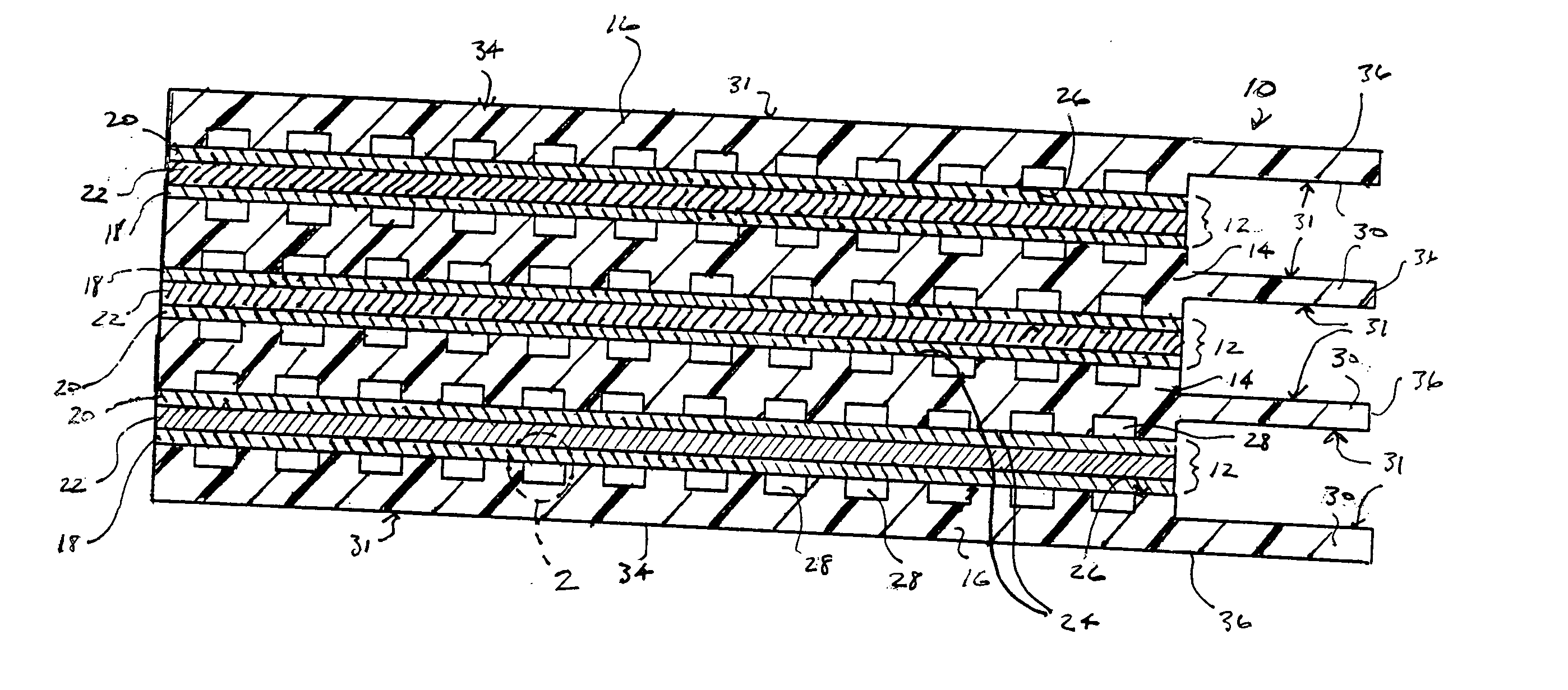
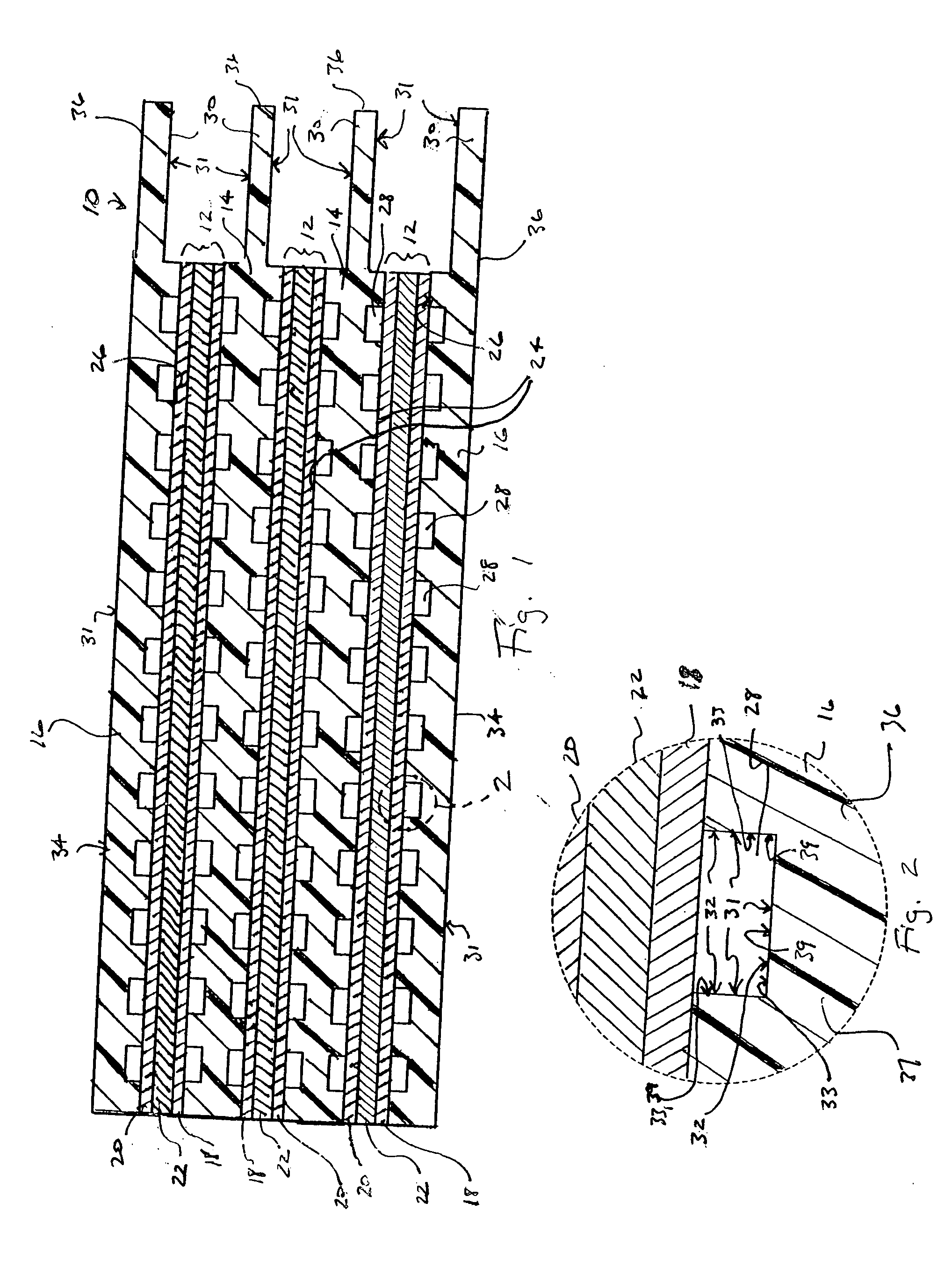
A portion of an embodiment of a fuel cell stack apparatus 10 according to the present invention is depicted in simplified cross section in FIG. 1. Fuel cell stack apparatus 10 generally includes membrane electrode assemblies 12, which are separated by bipolar plates 14. Single sided bipolar plates in the form of end plates 16 contain ...


PUM

PropertyMeasurementUnit
electrical potentialaaaaaaaaaa
pressureaaaaaaaaaa
electromagnetic energyaaaaaaaaaa

Abstract

A fuel cell component with surfaces having improved lyophilicity so that liquid on the component adheres closely to the surface in relatively flat droplets or sheets. The lyophilic surfaces may be formed with a thin layer of inherently lyophilic polymer on the surface of the component. The lyophilic surfaces may be selectively provided on critical areas of the component, such as for example on flow channel wall surfaces of bipolar plates and membrane electrode assemblies, thereby inhibiting liquid blocking of the flow channels during operation of the fuel cell.

Description

FIELD OF THE INVENTION The invention relates to fuel cells and more particularly, it relates to fuel cell components having lyophilic surfaces. BACKGROUND OF THE INVENTION Fuel cell technology has been the subject of much recent research and development activity due to the environmental and long-term fuel supply concerns associated with fossil fuel burning engines and burners. Fuel cell technology generally promises a cleaner source of energy that is sufficiently compact and lightweight to enable use in vehicles. In addition, fuel cells may be located close to the point of energy use in stationary applications so as to greatly reduce the inefficiency associated with energy transmission over long distances. Although many different reactants and materials may be used for fuel cells, all fuel cells generally have an anode and an opposing cathode separated by electrolyte. The anode and cathode generally have pores or channels so that reactant may be introduced into the cell through o...

Claims


Application Information

Patent Timeline
Patent Type & Authority Applications(United States)
IPC IPC(8): B05D5/12H01MH01M2/08H01M8/02
CPCH01M8/0206H01M8/0213H01M8/0215Y02E60/50H01M8/0226H01M8/0228H01M8/04171H01M8/0221B82Y30/00H01M8/02
Inventor EXTRAND, CHARLES W.
Owner ENTEGRIS INC
Why Eureka
Try Eureka