Spinal stabilization implant and method of application

a technology of stabilization implant and spine, which is applied in the field of spinal stabilization implant and method of application, can solve the problems of affecting the function of the involved joint, affecting the function of the affected joint, and affecting the function of the affected joint, and achieves the effect of minimal invasiveness

Inactive Publication Date: 2005-01-13
AESCULAP INC
View PDF25 Cites 115 Cited by
  • Summary
  • Abstract
  • Description
  • Claims
  • Application Information

AI Technical Summary

Benefits of technology

[0006] The present invention provides a system of spinal instrumentation used as an aid in bony fusion and stabilization of the spine in conjunction with minimally invasive spinal surgery not heretofore envisioned. The apparatus or system of the present invention is unique in that it permits placement, manipulation within the body and expansion and contraction of the implant to exert various pressures or forces on the spinal segment, but with minimally invasive techniques. This is made possible by the novel spinal implant assembly of the present invention, as well as the implant assembly insertion tool and system of the present invention which permits such minimally invasive techniques.

Problems solved by technology

This extensive exposure disrupts a considerable amount of tissue, particularly the lumbar paraspinal musculature which needs to be stripped off the vertebra bones for exposure.
This stripping leads to muscle damage directly caused by either electrical cautery or manual cutting or indirectly by interruption of vascular supply to the muscle due to coagulation or cutting of vessels, and caused also by embarrassment of the vascular supply during the course of surgery due to compression by retractors on the muscle which are required to maintain exposure.
In addition, spinal implants can impact upon the facet joints of the spine, particularly the upper most pair of pedicle screws, which can cause pain or dysfunction of the involved joint.
The present day surgical approach therefore has added to patient morbidity due to the extent of the surgical exposure, tissue damage done primarily to the posterior longitudinal musculature of the spine during the exposure, blood loss and risk of infection.
Large open operations also tend to be the cause of significant postoperative pain and disability.
Accordingly, these issues lead to longer hospital stays, higher postoperative complications, such as phlebitis and pneumonia brought on by immobility, and greater consumption of postoperative medications with their resultant side affects.
Also, interference by metal implants of the normal function of the rostral facet joints has been implicated in the early degeneration of these joints, as well as pain and disability, all which could lead to other more involved surgeries.

Method used


Image

  • Spinal stabilization implant and method of application
  • Spinal stabilization implant and method of application
  • Spinal stabilization implant and method of application

Examples


first embodiment

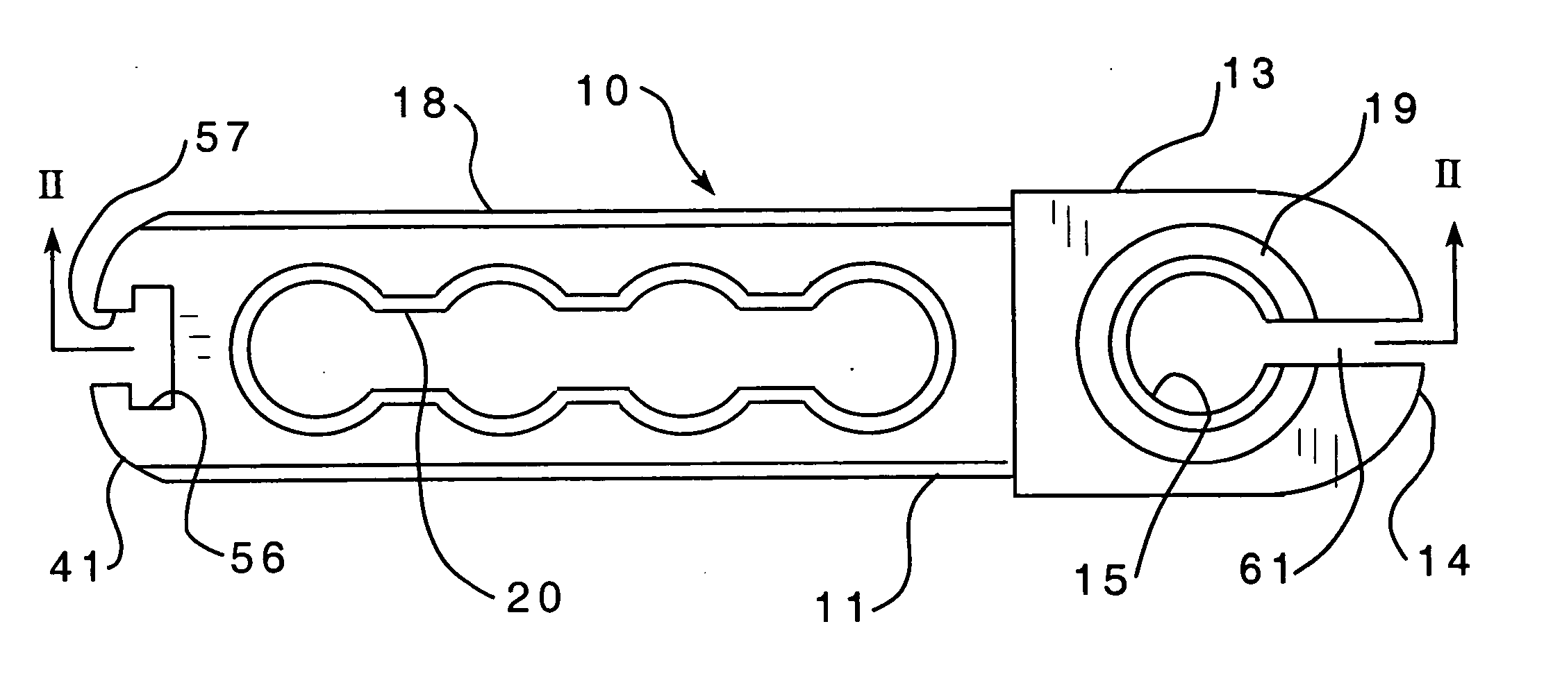
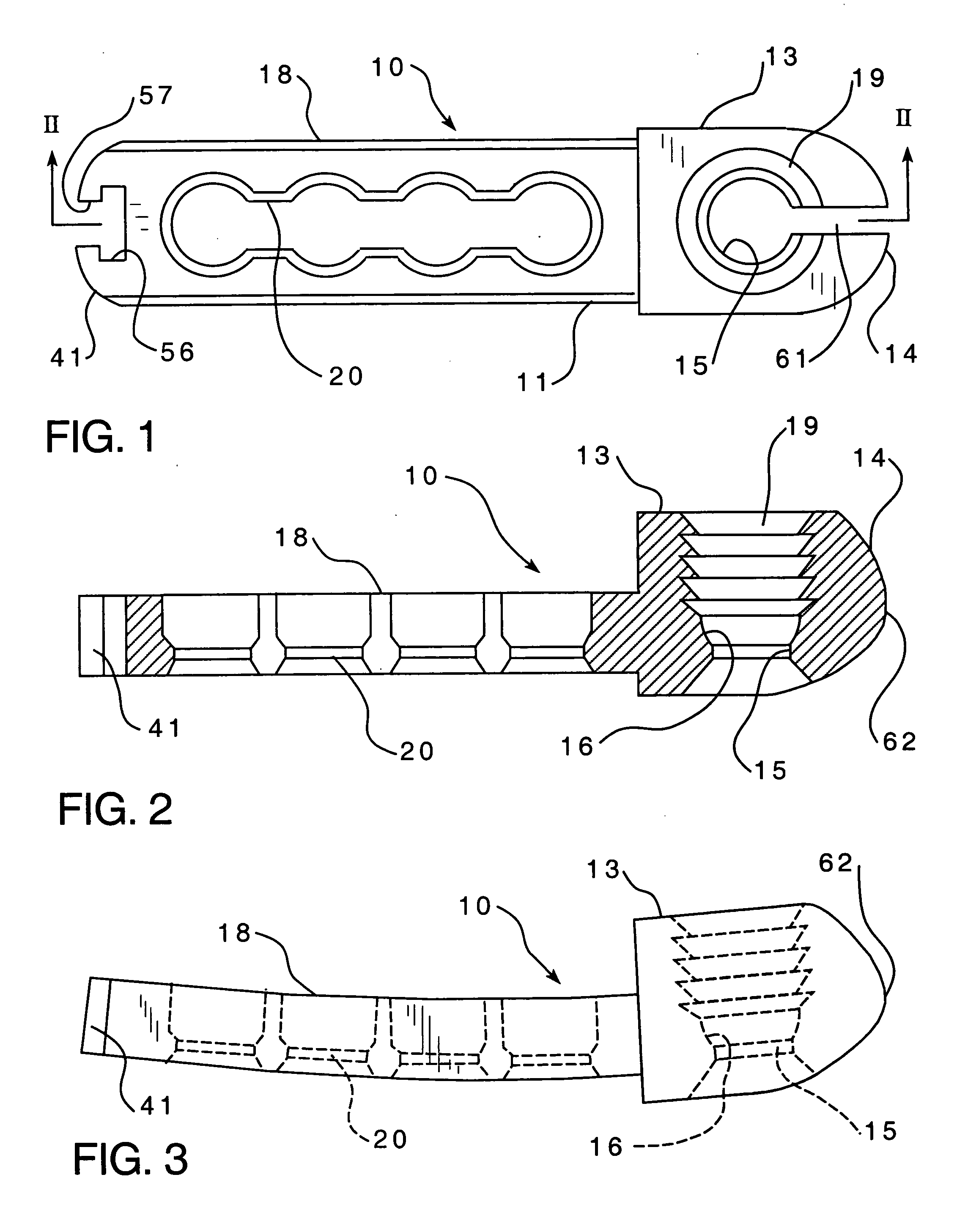
[0045] Referring next to FIGS. 12 through 16, the elongate insertion gun or tool 40 of the present invention is illustrated. This embodiment is referred to as the in line percutaneous version. The insertion tool 40 is releaseably securable to the proximal end 41 of arm 18 of plate assembly 10 whereby the tool 40 and elongate plate assembly 10 extend together end to end in their direction of elongation when secured together, as is best illustrated in FIGS. 13 and 14. Elongate insertion tool 40 is configured for manipulating plate assembly 10 as a whole and also for remotely manipulating screw receiving elements 13 and 21 for adjusting the distance between these elements. The purpose of the insertion tool 40 is to allow the surgeon a convenient tool to hold and control the spinal implant, to provide a mechanism for the minimally invasive placement of the implant, to provide a mechanism by which the spinal implant can be expanded so that it engages previously placed pedicle wires known...

second embodiment

[0073] Referring next to FIGS. 26, 27 and 28, the insertion tool is illustrated. In this embodiment the plate assembly 10 is releaseably retained at the distal end of the insertion tool 40′ for insertion through a minimally invasive access through skin and tissue of the patient by approaching the spinal column in a generally perpendicular attitude as is seen, for example, in U.S. patent application Publication No. US 2003 / 0208203.

[0074] This insertion tool 40′ of the present invention is provided with a tubular probe housing 80 with opposed anterior and posterior probe walls 81 and 82 respectively which respectively cover the distal end proximal ends 83 and 84 of plate assembly 10 when plate assembly 10 is in the reduced profile orientation illustrated in FIG. 28.

[0075] The distal end 85 of insertion tool 40′ is connected to plate assembly 10 whereby plate assembly 10 may be remotely oriented by manipulation from the insertion tool proximal end 86 from a reduced profile orientation...


PUM


Abstract

Vertebra bodies in the human spine are stabilized through the use of minimally invasive surgery for the implantation of an elongate implant plate assembly having spaced first and second screw receiving socket elements which are configured for respective attachment to first and second spaced vertebra with the aid of bone fixation screws and these elements are slidably received with respect to each other for adjustably changing the distance between the screw receiving socket elements. A lock assembly is also provided for selectively locking the first and second screw receiving elements from further relative sliding. An elongate insertion tool is releaseably secured to the plate assembly, and the insertion tool is configured for manipulating the plate assembly as a whole and for remotely manipulating the screw receiving socket elements for adjusting the distance therebetween. The plate assembly is inserted through an incision and manipulated and advanced with the insertion tool to provide minimally invasive insertion, and after fixation of the implant assembly with bone fixation screws is further utilized by remote manipulation to adjust the degree of compression on the vertebrae, and thereafter the implant is locked in position to prevent further relative movement between the screw receiving elements of the plate assembly.

Description

CROSS REFERENCE [0001] This is a continuation-in-part of U.S. patent application Ser. No. 10 / 615,196, filed Jul. 7, 2003 for SPINAL STABILIZATION IMPLANT AND METHOD OF APPLICATION.FIELD OF THE INVENTION [0002] The present invention relates generally to fixation systems for osteosynthesis of the spine, and more particularly, it pertains to a spinal implant system and a surgical procedure for inserting and applying the implant. BACKGROUND OF THE INVENTION [0003] Spinal surgery on the lumbar and thoracic spines have classically been open operations, meaning that the instrumentation used is placed through an incision that exposes all of the spine to be instrumented, as well as a portion of spine above and below the area to be instrumented due to the need for proper visualization. This extensive exposure disrupts a considerable amount of tissue, particularly the lumbar paraspinal musculature which needs to be stripped off the vertebra bones for exposure. This stripping leads to muscle da...

Claims


Application Information

Patent Timeline
Patent Type & Authority Applications(United States)
IPC IPC(8): A61B17/56A61B17/58A61B17/70A61B17/88
CPCA61B17/7059Y10S606/902A61B17/8023
Inventor DALTON, BRIAN E.
Owner AESCULAP INC
Why Eureka
Try Eureka