Layer with controlled grain size and morphology for enhanced wear resistance

a technology of grain size and morphology, applied in the field of cutting tool inserts, can solve the problems of increasing toughness of coatings, difficult to modify by conventional process adjustments, and difficult to meet the requirements of hard and brittle materials with limited plasticity, so as to achieve the effect of enhancing performance and wear resistan

Active Publication Date: 2005-01-20
SECO TOOLS AB
View PDF13 Cites 10 Cited by
  • Summary
  • Abstract
  • Description
  • Claims
  • Application Information

AI Technical Summary

Benefits of technology

According to this invention the grain size of MTCVD Ti(C,N) can be reduced, while simultaneously maintaining the columnar structure. In this way the problems with grain boundary sliding at higher temperatures will be reduced. Thus, the coating according to this invention consists of needle-like columnar crystals.
The fine-grained, columnar structure exhibits less grain boundary sliding than equiaxed coatings of the same grain size do at the same temperature and should be used in carbon steels or grey cast irons where wear resistance is important. Hence, the ideal situation in the above indicated wear resistance demanding applications is to control the deposition process so that the Ti(C,N) layer is composed of fine needle-like (columnar) grains. It has been found possible to control CVD process and the grain size and shape by using texture- and structure-modifying agents (referred to as dopants in this application) in such degree that these structures can be produced industrially.
The above mentioned coatings can be used in combination of other CVD materials such as alumina to enhance the performance and wear resistance of the prior-art products.

Problems solved by technology

The MTCVD coatings are, however, very difficult to modify by conventional process adjustments.
This relation is, however, not necessarily correct for hard and brittle materials with limited plasticity.
The CO-doped nanograined MTCVD coatings exhibited increased toughness, however, with reduced crater wear resistance as a consequence.

Method used


Image

  • Layer with controlled grain size and morphology for enhanced wear resistance
  • Layer with controlled grain size and morphology for enhanced wear resistance
  • Layer with controlled grain size and morphology for enhanced wear resistance

Examples


example 1

In this case only CO and ZrCl4 were applied to obtain columnar structures with controlled, reduced, gain size. The following five experimental coatings (referred to as coatings 1, 2, 3, 4 and 5) were produced at a pressure of 70 mbar and at a temperature of 880° C according to the process data given in Table 2. Compared with the U.S. Pat. No. 6,472,060, considerably lower amounts of doping were used except coating 5, which was produced according to prior art U.S. Pat. No. 6,472,060. In order to achieve fine-grained columnar structure, a maximum amount of CO should be less than 1%, preferably from about 0.1 to about 0.8%. In this example, 0.8% of CO was used (Coating 2). Coating 3 was deposited at CO doping level of 2.5% to obtain equiaxed grain morphology. Coating 4 was deposited using ZrCl4 doping to obtain columnar morphology. Coating 5 was deposited using 8% CO according to U.S. Pat. No. 6,472,060 to obtain a nanograined layer. Coating 1 was deposited according to prior art with...

example 2

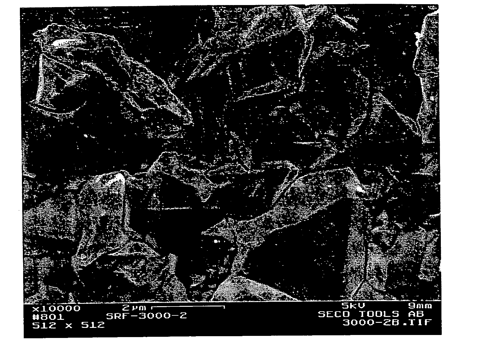
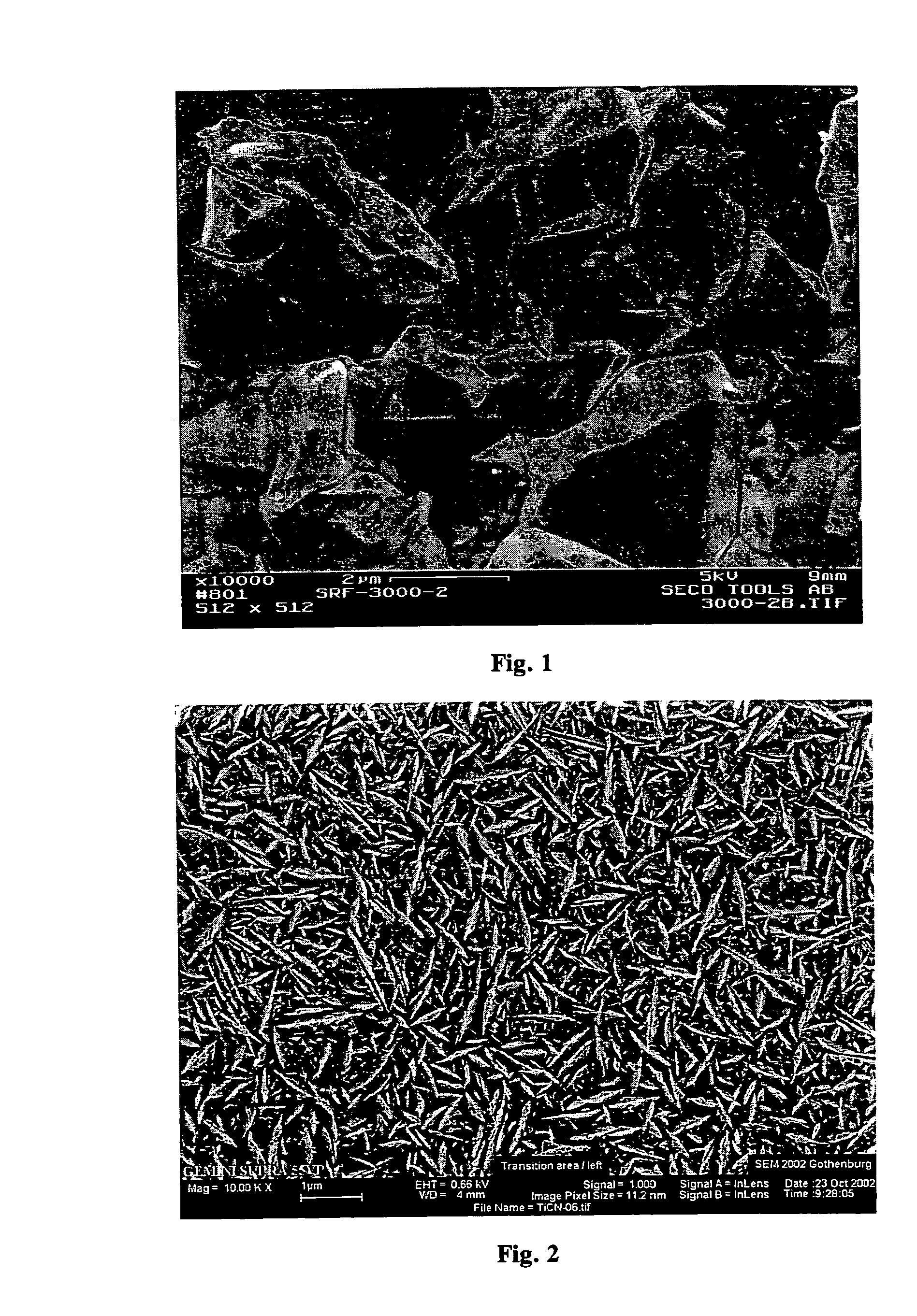
The coatings from Example 1 were investigated using Transmission electron microscopy (TEM) and Scanning electron microscopy (SEM) in order to elucidate the effect of CO and ZrCl4 doping on the grain size and morphology. It appeared clear even in SEM that the microstructure of the typical MTCVD Ti(C,N) coating being composed of large columnar crystals (FIG. 1) can be refined by CO doping. The obtained layer was composed of needle like crystals as shown in FIG. 2 at a CO doping level of 0.8%. Similar surface morphologies could be obtained either by ZrCl4 or HfCl4 doping alone or together with CO. The equiaxed grain morphology was obtained at CO doping level of 2.5%. TEM revealed that at this CO level the grain size was not brought into the nanograined region and was about 60 nm. Coating 4, which was deposited using ZrCl4 doping was composed of columnar grains with slightly smaller needle-like grains than Coating 2. The grain size of Coating 5 was in the nanograined region. The result...

example 3

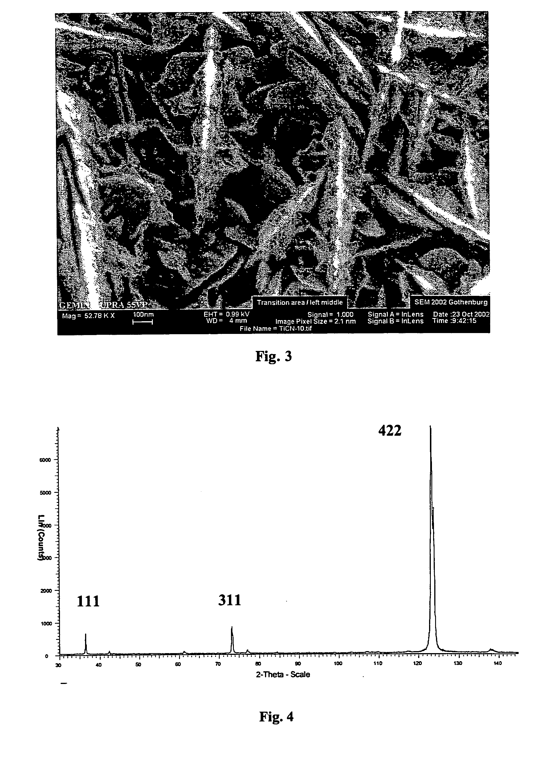
The following five experimental coatings (referred to as coatings 6, 7, 8, 9 and 10) were produced at a pressure of 70 mbar and at a temperature of 880° C. according to the process data given in Table 4. The coating thickness was 8 μm for all coatings. CO2 was not used in this particular example but could be applied with extreme care because coatings can in the presence of this precursor easily be brought into the nanograined region with equiaxed grain size.

The coatings were studied by using TEM together with EDS / WDS. The results are presented in Table 5. Surface morphology of Coating 9 is shown in FIG. 3.

TABLE 4H2N2CH3CNTiCl4ZrCl4(1 / min)(1 / min)(1 / min)(l / min)(%)AlCl3(%)CO2(%)CO(%)Coating 6balance45.50.552.10.10.00.00.0Coating 7balance45.50.552.10.30.00.00.0Coating 8balance45.50.552.10.30.00.00.5Coating 9balance45.50.552.10.51.50.00.0Coating 10balance45.50.552.10.51.50.00.5

TABLE 5Grain size*)MorphologyAnalysisCoating 670 × 650 nmNeedle-likeTraces of ZrCoating 755 × 750 nmNeedle-...


PUM

PropertyMeasurementUnit
grain widthaaaaaaaaaa
thicknessaaaaaaaaaa
thicknessaaaaaaaaaa

Abstract

Wear resistance of the prior-art Ti(C,N) layers can be considerably enhanced by optimising the grain size and microstructure. Considerably better wear resistance in, for example in many carbon steels, can be obtained by modifying the grain size and morphology of prior art MTCVD Ti(C,N) coatings. The improved coating is composed of small columnar crystals. Doping by using CO, CO2, ZrCl4, HfCl4 and AlCl3 or combinations of these can ensure the control of the grain size and shape. Doping has to be controlled carefully in order maintain the columnar structure and also in order to avoid nanograined structures and oxidisation. The preferred grain size should be in the sub-micron region with the grain width of from about 30 to about 300 nm. The length to width ratio should be more than 5, preferably more than 10 and the coating should exhibit a strong preferred growth orientation along 422 or 331. The XRD line broadening should be weak.

Description

BACKGROUND OF THE INVENTION The present invention relates to a cutting tool inserts consisting of a substrate at least partially coated with a coating consisting of one or more refractory layers of which at least one layer is a MTCVD-Ti(C,N)-layer composed of grains with grain size just above the nanograined region with columnar grain morphology. As a result the problem with grain boundary sliding at higher temperatures has been reduced and, consequently, wear resistance increased. The inserts are particularly useful in applications involving carbon steels or grey cast irons where wear resistance is important. Coated bodies used for metal cutting are well known. Typically, the bodies are made of a cemented carbide, cermet or ceramic and the coatings are one or more of a Group VIB metal carbide, nitride, oxide or mixtures thereof. For example, cemented carbides coated with layers of TiC, Ti(C,N), Al2O3 and TiN are widely used. There are many variations in layer composition and thic...

Claims


Application Information

Patent Timeline
Patent Type & Authority Applications(United States)
IPC IPC(8): C23C16/30C23C16/36C23C30/00
CPCC23C16/36C23C30/005Y10T428/30Y10T428/265Y10T428/252A01G9/025E02D29/0266E02D2600/20E02D2600/40Y02P60/20
Inventor RUPPI, SAKARI
Owner SECO TOOLS AB
Why Eureka
Try Eureka