
Biaxially oriented multi-layer laminated film and method for manufacture thereof

a laminated film, biaxial orientation technology, applied in the direction of synthetic resin layered products, instruments, other domestic objects, etc., can solve the problems of resins, insufficient strength, uniform drawing, delamination defects, etc., to achieve high interlayer adhesion and high tearing resistance

Inactive Publication Date: 2005-01-20
TEIJIN LTD
View PDF4 Cites 19 Cited by
  • Summary
  • Abstract
  • Description
  • Claims
  • Application Information

AI Technical Summary

Benefits of technology

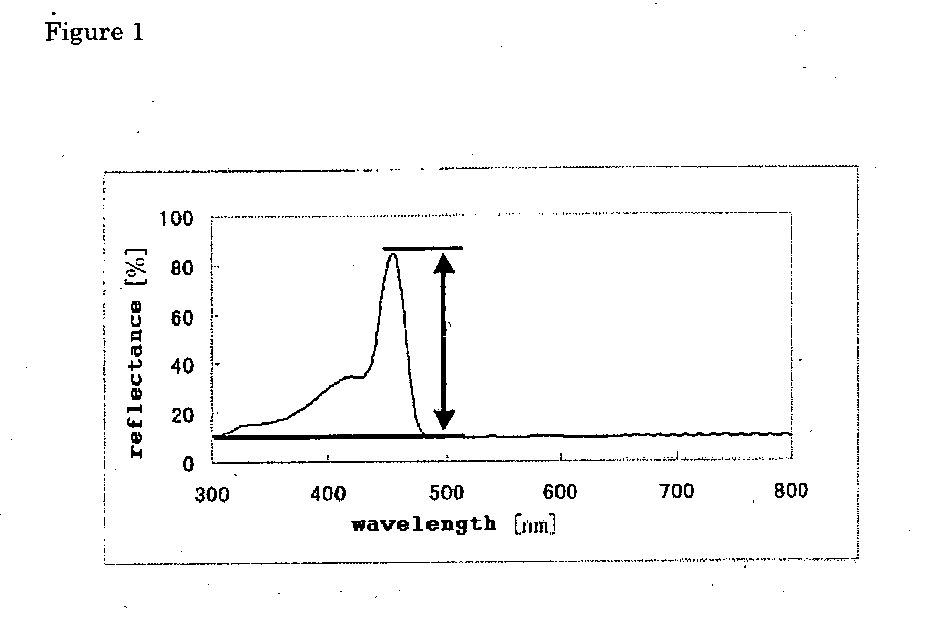
"The present invention solves the problems of conventional technology by providing a multilayer laminated film with high interlayer adhesivity and tearing resistance. The film has high reflectance of light in the wavelength range of 350 to 2,000 nm and a difference in reflectance of at least 20% compared to the base-line reflectance. The film has multiple melting points and a crystalline thermoplastic resin in the first layers and a different thermoplastic resin in the second layers. The film has at least one crystallization peak determined by differential scanning calorimetry. The production method involves alternately laminating layers of a crystalline thermoplastic resin and a thermoplastic resin with a lower melting point, drawing the laminate in both directions, and heat-setting it. The film has sufficient strength and interlayer adhesivity and a sufficient refractive index difference between the layers."

Problems solved by technology

However, these multilayer laminated films have poor adhesion between the layers to occasionally cause the delamination defect because resins having different compositions are combined with each other in these films to increase the refractive index difference between the layers.
Furthermore, the uniform drawing becomes difficult to form an easily tearable film having insufficient strength by the combination of resins having different compositions.
The concept of the conventional method to get the refractive index difference between layers by the refractive indices of the resins necessitates the selection of resins having considerably different compositions as the resins constituting the layers and the adhesivity between layers becomes poor.
The layer having low refractive index is essentially amorphous in these multilayer laminated film and these films have latent practical problems to fail in getting a sufficient interlayer adhesion even by the drawing treatment and in achieving uniform biaxial drawing in the plane directions to cause non-uniform properties.

Method used


Image

  • Biaxially oriented multi-layer laminated film and method for manufacture thereof

Examples


example 1

A polyethylene terephthalate having an intrinsic viscosity of 0.63 (in o-chlorophenol at 35° C.) (described as “PET” in the Table 1) was used as the polyester for the 1st layer and a copolymerized polyethylene terephthalate copolymerized with 12 mol % isophthalic acid and having an intrinsic viscosity of 0.61 (in o-chlorophenol at 35° C.) (described as “IA12PET” in the Table 1) was incorporated with 0.10 wt. % truly spherical silica particles (average particle diameter: 1.5 μm, major diameter to minor diameter ratio: 1.02, average deviation of particle diameter: 0.1) (described as “a” in the Table 1.) and the product was used as the polyester for the 2nd layer. The polyester for the 1st layer and the polyester for the 2nd layer were dried at 170° C. for 3 hours, supplied to respective extruders and melted by heating at 280° C. The polyester for the 1st layer was branched to 101 layers and the polyester for the 2nd layer was branched to 100 layers, the branched 1st layers and 2nd la...

examples 2 , 3 and 5 to 7

EXAMPLES 2, 3 and 5 to 7

The operations of the Example 1 were repeated except for the change of the polyester for the 2nd layer and the production conditions to those described in the Table 1. The term “IA8PET” described in the Table 1 as the kind of the resin of each layer is a polyethylene terephthalate copolymerized with 8 mol % isophthalic acid and having an intrinsic viscosity of 0.65 (in o-chlorophenol at 35° C.) and “IA20PET” is a polyethylene terephthalate copolymerized with 20 mol % isophthalic acid and having an intrinsic viscosity of 0.58 (in o-chlorophenol at 35° C.). The term “b” described in the Table 1 as the kind of the inert particle is bulk calcium carbonate (average particle diameter: 1.5 μm, major diameter to minor diameter ratio: 1.30, average deviation of particle diameter: 0.3) and the term (c) is truly spherical silicone particles (average particle diameter: 0.1 μm, major diameter to minor diameter ratio: 1.10, average deviation of particle diameter: 0.2).

T...

example 4

A polyethylene terephthalate having an intrinsic viscosity of 0.63 (in o-chlorophenol at 35° C.) (PET) was used as the polyester for the 1st layer and a copolymerized polyethylene terephthalate copolymerized with 10 mol % 2,6-naphthalenedicarboxylic acid and having an intrinsic viscosity of 0.70 (in o-chlorophenol at 35° C.) (described as “NDC10PET” in the Table 1) was prepared as the polyester for the 2nd layer. The polyester for the 1st layer and the polyester for the 2nd layer were dried at 170° C. for 3 hours, supplied to respective extruders and melted by heating at 280° C. The polyester for the 1st layer was branched to 101 layers and the polyester for the 2nd layer was branched to 100 layers, the branched 1st layers and 2nd layers were alternately laminated by using a multilayer feed block apparatus, guided to a die while keeping the laminated state, and cast on a casting drum to obtain an undrawn multilayer laminated film having a total layer number of 201 and composed of a...


PUM


Abstract

A film composed of a number of layers having different refractive indices and alternately laminated one upon another has characteristic optical properties by light interference. Conventional films having such structure have problems of poor interlaminar adhesivity and low tear strength. The problems are solved by a film having the following constitution. A biaxially drawn multilayer laminated film composed of alternately laminated 1st layers and 2nd layers at a total layer number of 11 or more. Each layer has a thickness of 0.05 to 0.5 μm. The 1st layer is made of a crystalline thermoplastic resin and the 2nd layer is made of a crystalline thermoplastic resin having a composition different from that of the resin constituting the 1st layer. The maximum light reflectance of the film within the wavelength range of 350 to 2,000 nm is higher than the base line reflectance obtained from a light reflectance curve within the wavelength range of 350 to 2,000 nm by 20% or over.

Description

TECHNICAL FIELD The present invention relates to a multilayer laminated film composed of alternately and regularly arranged layers having low refractive index and layers having high refractive index and selectively reflecting light of an arbitrary wavelength range according to the refractive index difference between the layers and the thickness of each layer. BACKGROUND TECHNOLOGY A multilayer laminated film composed of a number of layers having low refractive index and a number of layers having high refractive index alternately laminated one upon another may form an optical interference film selectively reflecting or transmitting light of a specific wavelength by the structural light interference between the layers. Such multilayer laminated film may form a film having excellent design by the structural color development, for example a pearlescent film having iridescent appearance by setting the wavelength of the selectively reflecting or transmitting light in a visible light ran...

Claims


Application Information

Patent Timeline
Patent Type & Authority Applications(United States)
IPC IPC(8): B32B7/023B32B7/027B32B27/08B32B27/36G02B1/11
CPCB32B27/08B32B27/36G02B1/111Y10T428/24942Y10S428/91Y10T428/2495Y10T428/269G02B1/115Y10T428/31786Y10T428/31794Y10T428/31504Y10T428/31797B32B7/023B32B7/027B32B2367/00B32B2307/518B32B2250/244
Inventor OYA, TARO
Owner TEIJIN LTD
Learn More