Chemical reaction device, chemical reaction system and chemical reaction method

Inactive Publication Date: 2005-01-20
HITACHI LTD
View PDF3 Cites 18 Cited by
  • Summary
  • Abstract
  • Description
  • Claims
  • Application Information

AI Technical Summary

Benefits of technology

[0010] In view of the problems to be obviated by the present invention as described above, the present invention attempts to increase the reaction efficiency and reduce the reaction time in the chemical reaction where molecules immobilized on the solid phase are reacted with the molecules in the solution, or in the chemical analysi

Problems solved by technology

When a narrow channel is used in such a case, the time of the solution passing over the area where the particular molecule has been immobilized will be reduced and diffusion of the reactant molecules in the solution will be insufficient, presumably resulting i

Method used


Image

  • Chemical reaction device, chemical reaction system and chemical reaction method
  • Chemical reaction device, chemical reaction system and chemical reaction method
  • Chemical reaction device, chemical reaction system and chemical reaction method

Examples


first embodiment

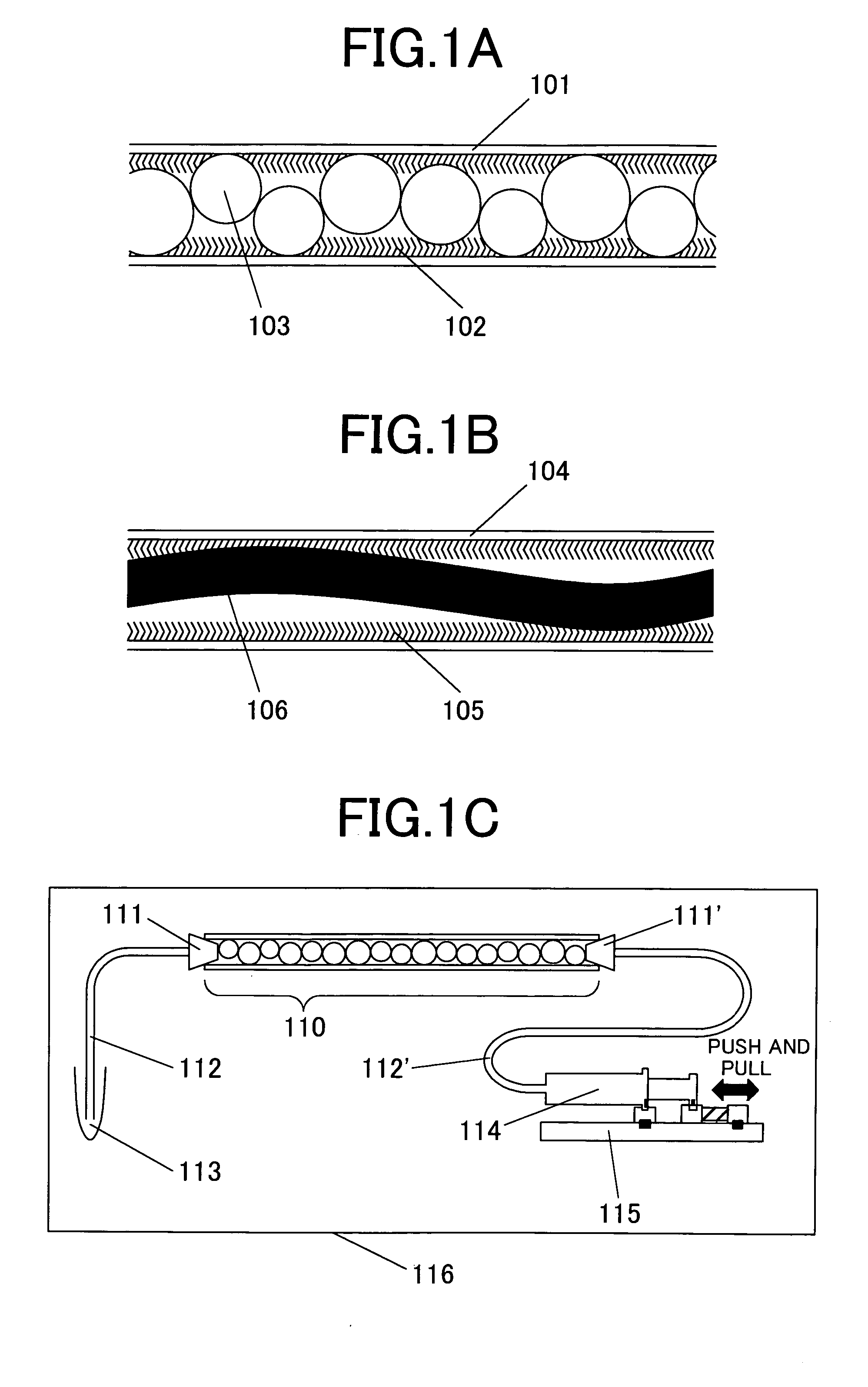
[0029]FIG. 1C is a view schematically showing the structure of the entire chemical reaction system produced by using the chemical reaction device according to the present invention. A reaction vessel 110 is the one described by referring to FIG. 1A comprising the capillary 101 having the enzyme 102 immobilized on its interior surface and filled with the glass beads 103. On opposite ends of the reaction vessel 110 are provided connectors 111 and 111′ which prevent exit of the glass beads 103 filled in the reaction vessel 110 from the reaction vessel 110 while feeding the solution to the reaction vessel 110, and these connectors 111 and 111′ also join the reaction vessel 110 with feed capillaries 112 and 112′. A sample tube 113 filled with the reaction solution containing the molecule which serves the substrate for the enzymatic reaction is provided at the end of the feed capillary 112, and a syringe 114 of a syringe pump 115 is provided at the end of the feed capillary 112′. When the...

second embodiment

[0035]FIG. 5 schematically shows the structure of the chemical analysis device according to the present invention. FIG. 5A is a total view of DNA measurement device in the form of a chip. This device comprises a flat slide glass 302 and a polydimethylsiloxane (PDMS) substrate 301 adhered to the slide glass 302, and the PDMS substrate 301 has a channel 303 formed therein to provide the site of the chemical reaction and simultaneously, the site of the detection. The slide glass 302 has a size of 25 mm×75 mm, and a thickness of about 1 mm. A nonfluorescent product comprising crown glass was used for the slide glass 302 for the subsequent fluorometric measurement. The PDMS substrate 301 has a thickness of about 2 mm, and it covers the slide glass 302 except for the margin of about 2 mm along the long sides of the slide glass 302. The regions of the slide glass 302 not covered by the PDMS substrate 301 are used as the gripper region for holding the device while it is inserted in the DNA ...


PUM

PropertyMeasurementUnit
Fractionaaaaaaaaaa
Flow rateaaaaaaaaaa
Diameteraaaaaaaaaa

Abstract

A chemical reaction device is provided for a chemical reaction between molecules immobilized on a solid phase and molecules in a solution, and a chemical analysis device is also provided to capture molecules in the solution by molecules immobilized on the solid phase through a chemical reaction and subsequent measurement of the captured molecules. Reaction efficiency as well as sample throughput are thereby improved. The chemical reaction device and the chemical analysis device use a channel of a microfluidic device for a reaction vessel, and at least a particular molecule is immobilized on an interior surface and a fixed structure or a non-fixed obstacle against a flow is provided in the channel. In a typical reaction vessel having an enzyme immobilized on an interior surface of a capillary and glass beads functioning as an obstacle for the flow filled in the channel of the capillary, a reaction solution can move either in one direction or back and forth in two directions to thereby undergo a reaction with the enzyme immobilized on the interior surface. The flow of the reaction solution is not a laminar flow so that a reaction between the particular molecule immobilized and the reaction solution proceeds at high efficiency.

Description

CROSS-REFERENCE TO RELATED APPLICATIONS [0001] This application is related to U.S. application Ser. No. 10 / 750886 filed on Jan. 5, 2004, U.S. application Ser. No. 10 / 788440 filed on Mar. 1, 2004, and U.S. application Ser. No. 10 / 790063 filed on Mar. 2, 2004, the disclosures of which are hereby incorporated by reference.CLAIM OF PRIORITY [0002] The present application claims priority from Japanese application JP 2003-196178 filed on Jul. 14, 2003, the content of which is hereby incorporated by reference into this application. FIELD OF THE INVENTION [0003] This invention relates a chemical reaction device, a chemical reaction system, and a chemical reaction method. More specifically, this invention relates to a chemical reaction device, a chemical reaction system, and a chemical reaction method wherein a chemical reaction in a minute space is utilized. This invention also relates to a chemical reaction device, a chemical reaction system, and a chemical reaction method wherein a biolog...

Claims


Application Information

Patent Timeline
IPC IPC(8): G01N33/53C12M1/00C12N15/09G01N33/543G01N37/00
CPCG01N33/54366
Inventor KOHARA, YOSHINOBUOKANO, KAZUNORINODA, HIDEYUKI
Owner HITACHI LTD
Why Eureka
Try Eureka