High power, high linearity and low insertion loss single pole double throw trasmitter/receiver switch

a transmitter/receiver switch, high linearity technology, applied in the direction of electronic switching, waveguides, pulse techniques, etc., can solve the problems of power loss and harmonic distortion, limit the control voltage, reduce the pinch-off voltage approach or increase the control voltage approach, etc., to suppress harmonic distortion and effectively improve power-handling capability.

Inactive Publication Date: 2005-01-20
ANALOG DEVICES INC
View PDF7 Cites 50 Cited by
  • Summary
  • Abstract
  • Description
  • Claims
  • Application Information

AI Technical Summary

Benefits of technology

A fourth aspect of the present invention is a radio frequency single pole double throw switch. The radio frequency single pole double throw switch includes a receiver port; a transmitter port; an antenna port; a receiver section connecting the receiver port to the antenna; and a transmitter section connecting the transmitter port to the antenna. The receiver section includes a plurality of dual-gate field effect transistors connected in series, each dual-gate field effect transistor including two gates, a source, and a drain such that one of the series connected dual-gate field effect transistors has a modified gate therein that is of a different size from gates of other series connected dual-gate ...

Problems solved by technology

Therefore, FET 5 is not able to remain in the OFF state at all times, causing power loss and harmonic distortion.
However, the battery used in conventional cellular handset applications, as mentioned above, limits the control voltage.
Therefore, the lowering of the pinch-off vol...

Method used


Image

  • High power, high linearity and low insertion loss single pole double throw trasmitter/receiver switch
  • High power, high linearity and low insertion loss single pole double throw trasmitter/receiver switch
  • High power, high linearity and low insertion loss single pole double throw trasmitter/receiver switch

Examples


Embodiment Construction

The present invention will be described in connection with preferred embodiments; however, it will be understood that there is no intent to limit the present invention to the embodiments described herein. On the contrary, the intent is to cover all alternatives, modifications, and equivalents as may be included within the spirit and scope of the present invention as defined by the appended claims.

For a general understanding of the present invention, reference is made to the drawings. In the drawings, like reference numbering has been used throughout to designate identical or equivalent elements. It is also noted that the various drawings illustrating the present invention are not drawn to scale and that certain regions have been purposely drawn disproportionately so that the features and concepts of the present invention could be properly illustrated.

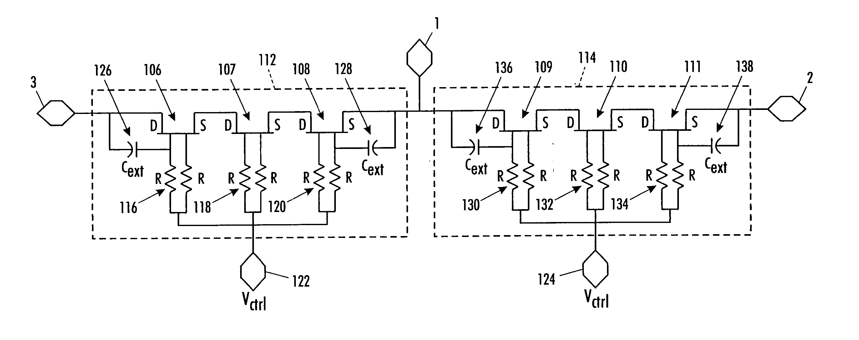
As will be described below, the transmitter-receiver (T / R) switch of the present invention can be constructed of field effect tra...


PUM


Abstract

A high performance single-pole-double-throw (SPDT) Transmitter/Receiver (T/R) FET switch utilizes a plurality of multi-gate FETs in series to realize low insertion loss, low harmonic distortion and high power handling capabilities. The SPDT switch consists of an antenna port, a transmitter branch coupled to a transmitter port through a plurality of multi-gate FETs in series and a receiver branch coupled to a receiver port through a plurality of multi-gate FETs in series. When a high power signal passes from the transmitter port to the antenna port through the transmitter branch, the receiver branch is required to be shut off electrically to prevent the high power signal from leaking to receiver port. This leakage can degrade the isolation of the switch and cause harmonic distortion. Furthermore, the transmitter branch is required to provide a resistance as small as possible to reduce the power loss when it passes through the transmitter branch to the antenna port. In the receiver branch, two of the gate metals in the multi-gate FETs are fabricated with gate sizes several times larger than the others. Furthermore, a heavily doped cap layer is utilized between the gate fingers in a multi-gate FET to reduce the channel resistance of FET, thereby lowering the insertion loss.

Description

FIELD OF THE PRESENT INVENTION The present invention relates to high frequency semiconductor switches used for wireless communication systems, and more particularly, to high-electron-mobility-transistor (“HEMT”) switches to meet the criteria of high power, low insertion loss, and low distortion performance. BACKGROUND OF THE PRESENT INVENTION In conventional mobile wireless communication systems, especially Global System for Mobile Communications (“GSM”) cellular handsets, the transmit / receive (“T / R”) switch applied to the antenna end is capable of handling a high power signal of up to 35 dBm along with low harmonic distortion and low signal loss. The conventional mobile wireless communication systems further use a control voltage to actuate the switching wherein the control voltage is limited by the handset battery voltage, which in most conventional situations is about 3 volts and, in some cases, even less. FIG. 1 illustrates a schematic diagram of a conventional single pole dou...

Claims


Application Information

Patent Timeline
IPC IPC(8): H03K17/687H03K17/693
CPCH03K17/6871H03K17/102H03K17/693
Inventor ZHAO, YIBINGZHANG, SHUYUNMCMORROW, ROBERT J.
Owner ANALOG DEVICES INC
Why Eureka
Try Eureka