Coated medical device and method for manufacturing the same

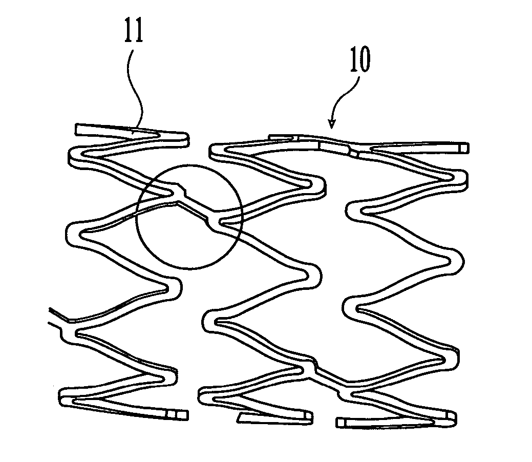
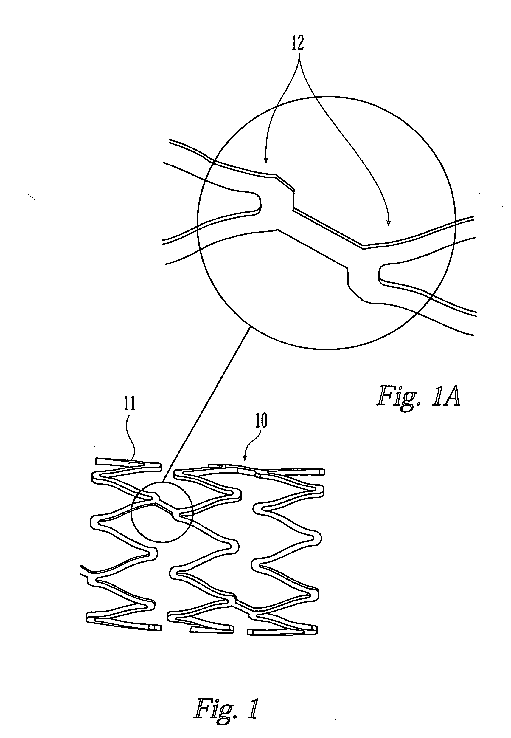
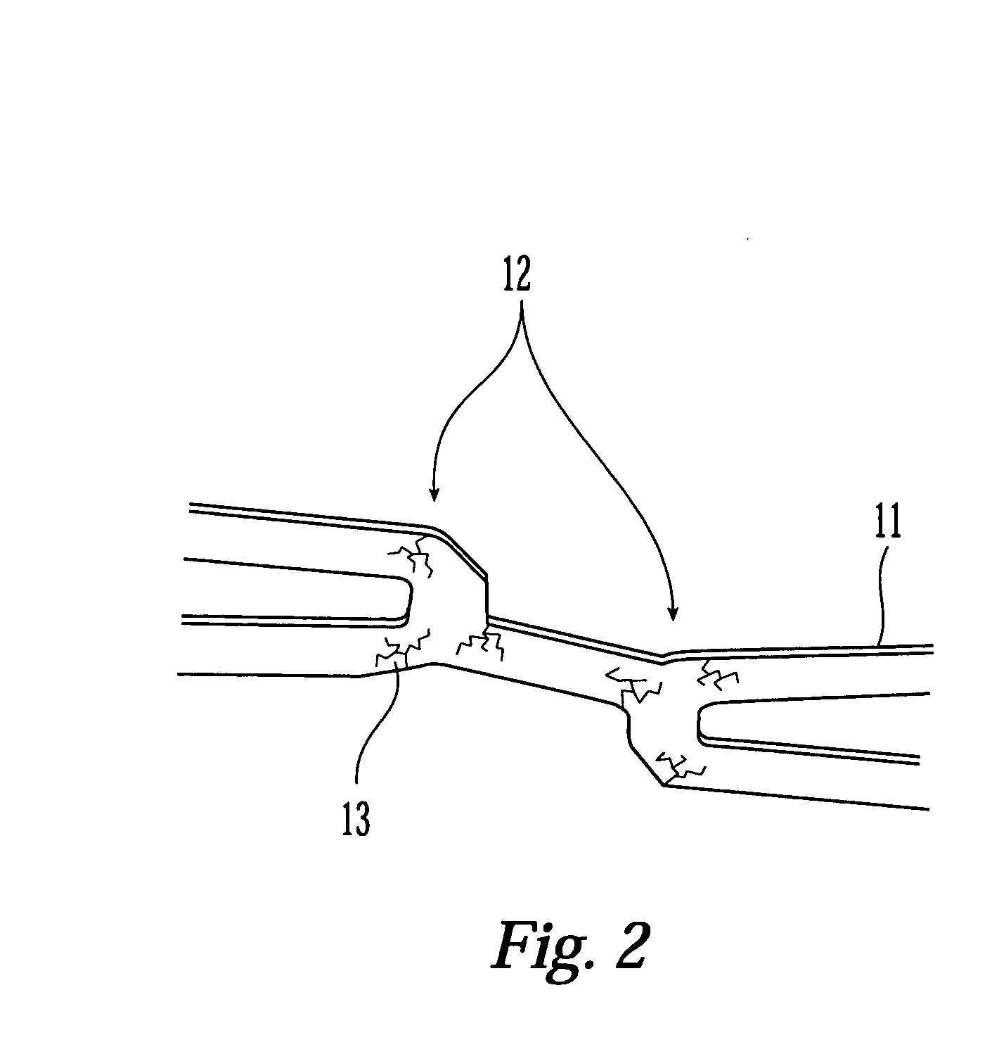
a medical device and coating technology, applied in the field of coating medical devices, can solve the problems of cracks in the coating, the polymer coating on the stent is in a condition like glass and is particularly vulnerable to stress cracking, and the coating can exhibit cracks

Active Publication Date: 2005-01-20
BOSTON SCI SCIMED INC
View PDF32 Cites 127 Cited by
  • Summary
  • Abstract
  • Description
  • Claims
  • Application Information

AI Technical Summary

Benefits of technology

[0012] In another embodiment, the system for coating a medical device comprises a coating material source containing a coating material, a first roller having a surface and a second roller having a surface. The first roller is situated relative to the coating material source so that the coating material in the coating material source can be transferred to the first roller surface. The first roller and second roller are situated relative to each other so that the first roller can transfer the coating material transferred to the first roller surface to the second roller surface. The second roller is situated relative to the tubular portion so that the second roller can transfer the coating material transferred to the second roller surface to the outer surface of the tubular portion. The surface of the second roller can be rougher than the surface of the first roller. Preferably, the first roller contacts the surface of the second roller and the surface of the second roller contacts the outer surface of the tubular portion. Also the system can include a mechanism for removing exce...

Problems solved by technology

However, the coatings for a medical device can exhibit problems of cracking especially when the device is exposed to harsh conditions, such as low temperatures and/or mechanical deformations.
Therefore, when chilled to these temperatures, a polymer coating on the stent is in a condition like glass and particularly vulnerable to stress-cracking when the device is processed.
Cracks in the coating are undesirable because they can cause the coating to flake or separate from the coated surface of the device while the coated medical device is inside the body of a patient.
Such separated or loose pieces of coating can cause emboli.
When the sheath is withdrawn, the adhered coating may be torn or removed from the coated device.
Also, the conventional methods for coating medical...

Method used


Image

  • Coated medical device and method for manufacturing the same
  • Coated medical device and method for manufacturing the same
  • Coated medical device and method for manufacturing the same

Examples


Embodiment Construction

[0034] 1. Suitable Medical Devices

[0035] The medical devices of the present invention can be inserted and may be implanted into the body of a patient. The medical devices suitable for the present invention include, but are not limited to, stents, surgical staples, catheters, such as central venous catheters and arterial catheters, guidewires, cannulas, cardiac pacemaker leads or lead tips, cardiac defibrillator leads or lead tips, implantable vascular access ports, blood storage bags, blood tubing, vascular or other grafts, intra-aortic balloon pumps, heart valves, cardiovascular sutures, total artificial hearts and ventricular assist pumps, and extra-corporeal devices such as blood oxygenators, blood filters, hemodialysis units, hemoperfusion units and plasmapheresis units.

[0036] Medical devices of the present invention include those that have a tubular or cylindrical-like portion. The tubular portion of the medical device need not to be completely cylindrical. For instance, the ...


PUM

PropertyMeasurementUnit
Fractionaaaaaaaaaa
Fractionaaaaaaaaaa
Fractionaaaaaaaaaa

Abstract

The medical device of the invention comprises a surface comprising at least one outermost portion and a plurality of depressions. The depressions occupy at least about 80% of the surface area of the surface. The depressions contain a coating material that preferably comprises a biologically active material and/or polymer, and the outermost portion is substantially free of any coating material. The invention is also directed to a method for manufacturing a medical device. The method comprises applying a coating material to the surface of the medical device by using at least one roller.

Description

FIELD OF THE INVENTION [0001] This invention relates generally to medical devices having a coating. The medical device is capable of delivering a biologically active material to a desired location within the body of a patient. More particularly, the invention is directed to medical devices having a surface comprising at least one outermost portion and a plurality of depressions. The depressions contain a coating material preferably comprising a biologically active material, and the outermost portions are substantially free of any coating material. The invention is also directed to a method and system for manufacturing a coated medical device involving the use of roller(s). BACKGROUND OF THE INVENTION [0002] It has been proposed that a variety of medical conditions can be treated by introducing an insertable or implantable medical device having a coating for release of a biologically active material. For example, various types of drug-coated stents have been proposed for localized de...

Claims


Application Information

Patent Timeline
IPC IPC(8): A61F2/00A61F2/06A61F2/90B05C1/02B05C1/08B05C1/14B05D1/28
CPCA61F2/91A61L2420/08A61F2002/91533A61F2002/91558A61F2250/0068A61L31/10A61L31/14A61L31/16A61L2300/606B05C1/022B05C1/08B05C1/14B05D1/28B05C1/0813B05C1/0817A61F2/915
Inventor AUSTIN, MICHAELROBINSON, DONBOULAIS, DENNIS R.KULKARNI, PRAVEENFREYMAN, TOBYEPSTEIN, SAMUEL J.NAIMARK, WENDYSCHWARZ, MARLENE
Owner BOSTON SCI SCIMED INC
Why Eureka
Try Eureka