Spinal implants

a technology for spinal implants and implants, which is applied in the field of spinal implants, can solve the problems of herniation, shrinkage or displacement of the disc, and present risks to the patient, and achieve the effects of improving handling, enhancing bone growth, and increasing structural stability

Inactive Publication Date: 2005-01-20
EUROPEAN BIOINFORMATICS INSTITUTE
View PDF20 Cites 30 Cited by
  • Summary
  • Abstract
  • Description
  • Claims
  • Application Information

AI Technical Summary

Benefits of technology

It has been found that the implants of this invention afford benefits compared to implants among those known in the art. Such benefits include enhanced promotion of bone growth after implantation, increased structural stability after implantation, and improved handling and reduced breakage during surgical procedures. Specific benefits and embodiments of the present invention are apparent from the detailed description set forth herein. It should be understood, however, that the detailed description and specific examples, while indicating embodiments among those preferred, are intended for purposes of illustration only and are not intended to limit the scope of the invention.

Problems solved by technology

Degeneration may result in shrinkage or displacement (“slipping” or herniation) of the disk.
A cylindrical cutting tool is typically used to prepare the cervical site to receive the dowel, However, autologous implants are, in many situations, impractical and present risks to the patient because they require a second surgical site and potential damage to the bone from which the graft is harvested.
However, when using allografts, the potential of disease transmission and tissue rejection must be considered.
However, spinal implants among those known in the art lack one or more of these characteristics.

Method used


Image

  • Spinal implants
  • Spinal implants
  • Spinal implants

Examples


example 1

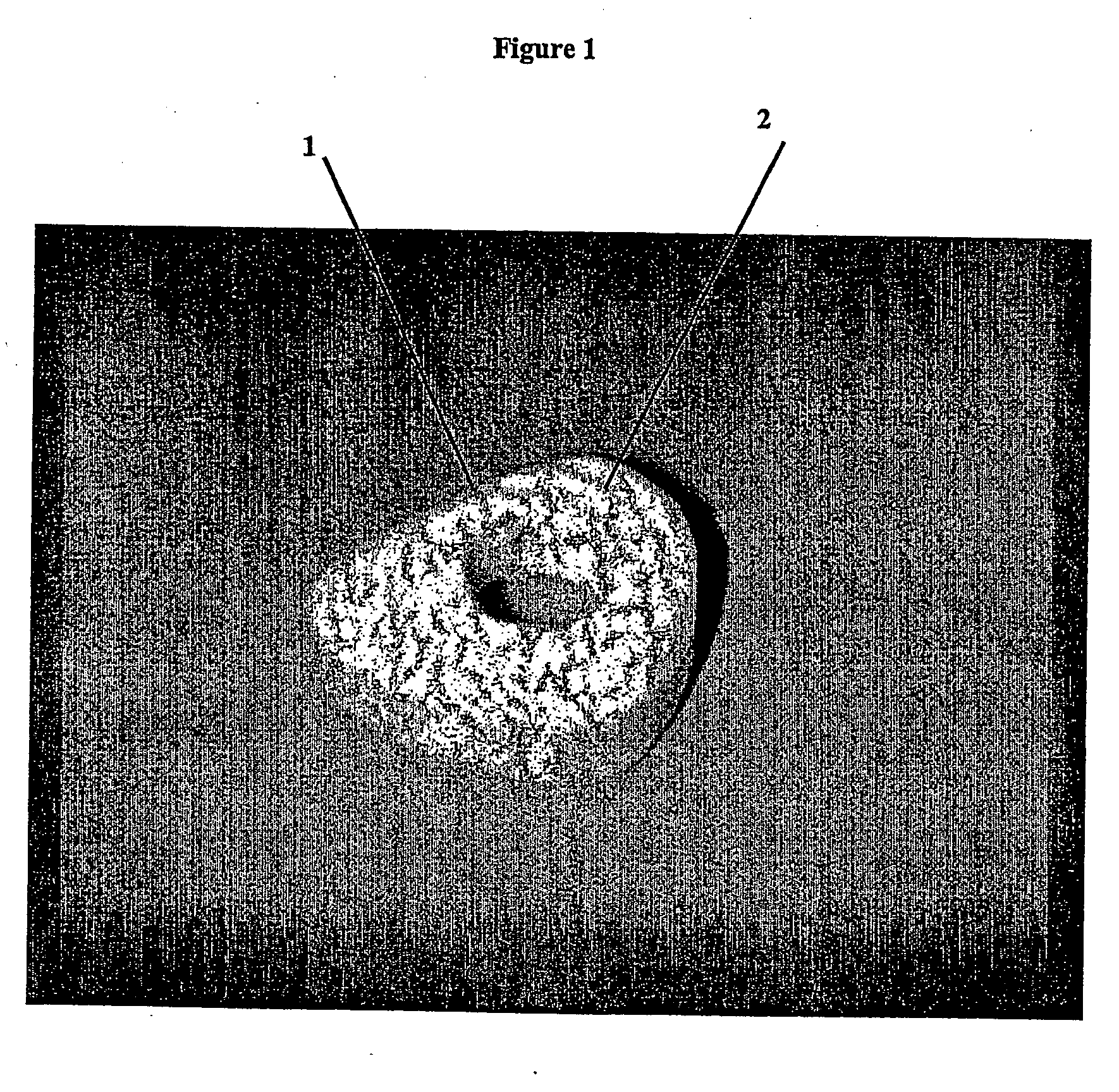
An implant is made by cutting an approximately 12 mm transverse segment from the fibula of a human cadaver to form an implant body. The body is substantially disk shaped, forming a ring having a diameter of approximately 12 mm. The top and bottom surfaces of the body are textured, to form concentric rings, using a concentric-arc ridge cutter. The edges of the body are then filed to form a bevel around the entire circumference of the segment.

The implant is then suspended in a vessel and immersed in 1.0 N HCl, at a ratio of 100 ml HCl per gram of bone. The acid is stirred, and maintained at ambient temperature (approximately 21° C.) for approximately two hours. The depth of demineralization is measured and determined to be approximately 1 mm. The implant is washed in buffered saline. The washing step is repeated three times, and the implant is then soaked in buffered saline for about 10 minutes. The implant is freeze dried and stored in a sterile container.

The implant is then sur...

example 2

An implant is made by cutting an approximately 20 mm transverse segment from the femur of a human cadaver to form an implant body. The body is substantially disk-shaped, forming a ring having a diameter of approximately 25 mm. The top and bottom surfaces of the body are textures, to form concentric rings, using a concentric-arc ridge cutter. Six radial channels, approximately 0.5 mm wide and approximately 0.8 mm deep are cut into the top and bottom surfaces of the implant using a saw. The edges of the body are filed to form a bevel around the entire circumference of the segment.

The implant is then suspended in a vessel and immersed in 1.0 N HCl, at a ratio of 100 ml HCl per gram of bone. The acid is stirred, and maintained at ambient temperature (approximately 21° C.) for approximately seven hours. The depth of demineralization is measured and determined to be approximately 2 mm. The implant is washed in buffered saline. The washing step is repeated three times, and the implant i...

example 3

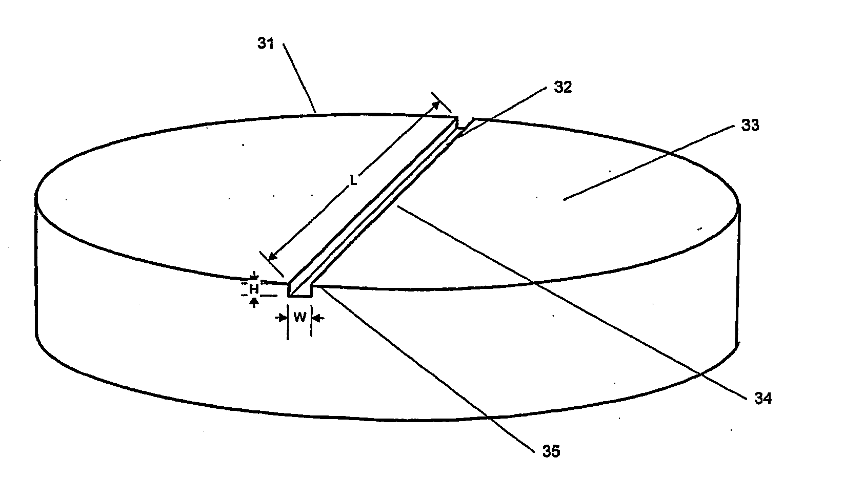
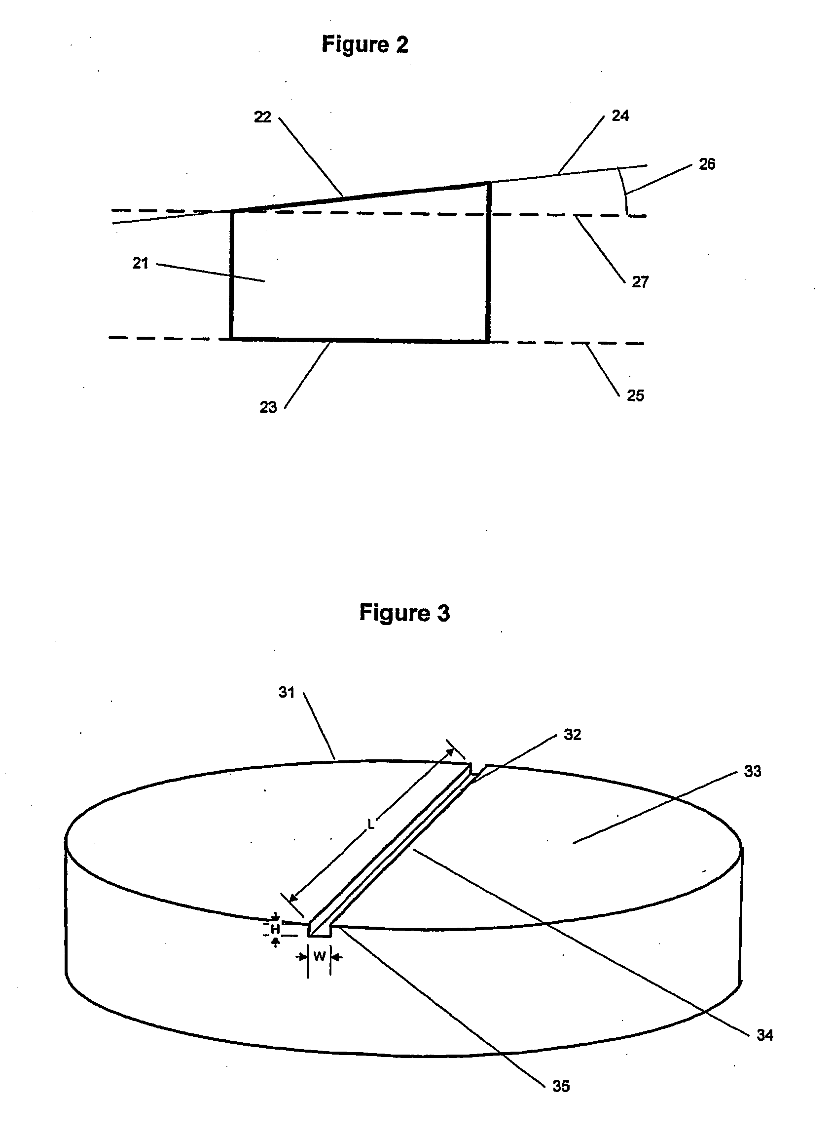
An implant is made by cutting an approximately 24 mm transverse segment from the femur of a human cadaver to form an implant body. The body is substantially disk shaped, forming a ring having a diameter of approximately 25 mm. The edges of the body are filed to form a bevel around the entire circumference of the segment. The body is then cut in half, to form two half-ring implants.

The implants are then suspended in a vessel and immersed in 1.0 N HCl, at a ratio of 100 ml HCl per gram of bone. The acid is stirred, and maintained at ambient temperature (approximately 21° C.) for approximately seven hours. The depth of demineralization is measured and determined to be approximately 2 mm. The implants are washed in buffered saline. The washing step is repeated three times, and the implants are then soaked in buffered saline for about 10 minutes.

The top and bottom surfaces of the body are textured, to form concentric rings, using a concentric-arc ridge cutter. The implants are freez...


PUM

PropertyMeasurementUnit
depthaaaaaaaaaa
depthaaaaaaaaaa
diameteraaaaaaaaaa

Abstract

Spinal implants having at least one of several attributes, including a surface layer of demineralized bone, a beveled edge, and channels in the faces in contact with adjacent vertebral bodies. Preferably, the implant has a generally planar top surface, a generally planar bottom surface, and a side surface, wherein at least one of the top and bottom surfaces is demineralized to a depth of from 0.8 mm to 3 mm. Preferably, the top and bottom surfaces of the implant are textured. Also preferably, the implant is disk shaped and comprises an insertion side extending at least 10% of the circumference of the implant, wherein the edge formed by the insertion side and the top surface, and the edge formed by the insertion side and the bottom surface, are beveled.

Description

FIELD OF THE INVENTION The present invention generally relates to devices for use in orthopedic surgical procedures, and more particularly to spinal implants and methods of manufacture. BACKGROUND OF THE INVENTION During the course of treating many spinal disorders it frequently becomes necessary to permanently secure vertebrae in a relatively fixed position. Such disorders may arise as a result of disease, trauma, or congenital deformation. One group of such disorders results from the degeneration of one or more intervertebral disks, which are layers of fibrocartilage between the adjacent vertebrae. Degeneration may result in shrinkage or displacement (“slipping” or herniation) of the disk. As a result, the spinal cord and emergent nerves can become compressed, due to misalignment of the vertebrae or pressure from displaced disk material, with chronic and sometimes debilitating, neck, back, and peripheral pain. One method of treatment for intervertebral disk degeneration involve...

Claims


Application Information

Patent Timeline
Patent Type & Authority Applications(United States)
IPC IPC(8): A61F2/00A61F2/28A61F2/30A61F2/44A61F2/46A61L27/36
CPCA61F2/28A61L2430/38A61F2/30771A61F2/44A61F2/442A61F2/4465A61F2002/2817A61F2002/2821A61F2002/2839A61F2002/30057A61F2002/30059A61F2002/30112A61F2002/30138A61F2002/30153A61F2002/302A61F2002/30202A61F2002/30225A61F2002/3023A61F2002/30235A61F2002/3082A61F2002/30827A61F2002/30836A61F2002/30904A61F2002/4649A61F2230/0004A61F2230/0017A61F2230/0019A61F2230/0065A61F2230/0069A61F2310/00365A61F2310/00958A61L27/3608A61L27/3658A61L27/3683A61F2/30767
Inventor SCHWARDT, JEFFREYD'ANTONIO, PAUL
Owner EUROPEAN BIOINFORMATICS INSTITUTE
Why Eureka
Try Eureka