

Apparatus and method for machining of hard metals with reduced detrimental white layer effect
- Summary
- Abstract
- Description
- Claims
- Application Information
AI Technical Summary
Benefits of technology
Problems solved by technology
Method used
Image

Examples
Embodiment Construction
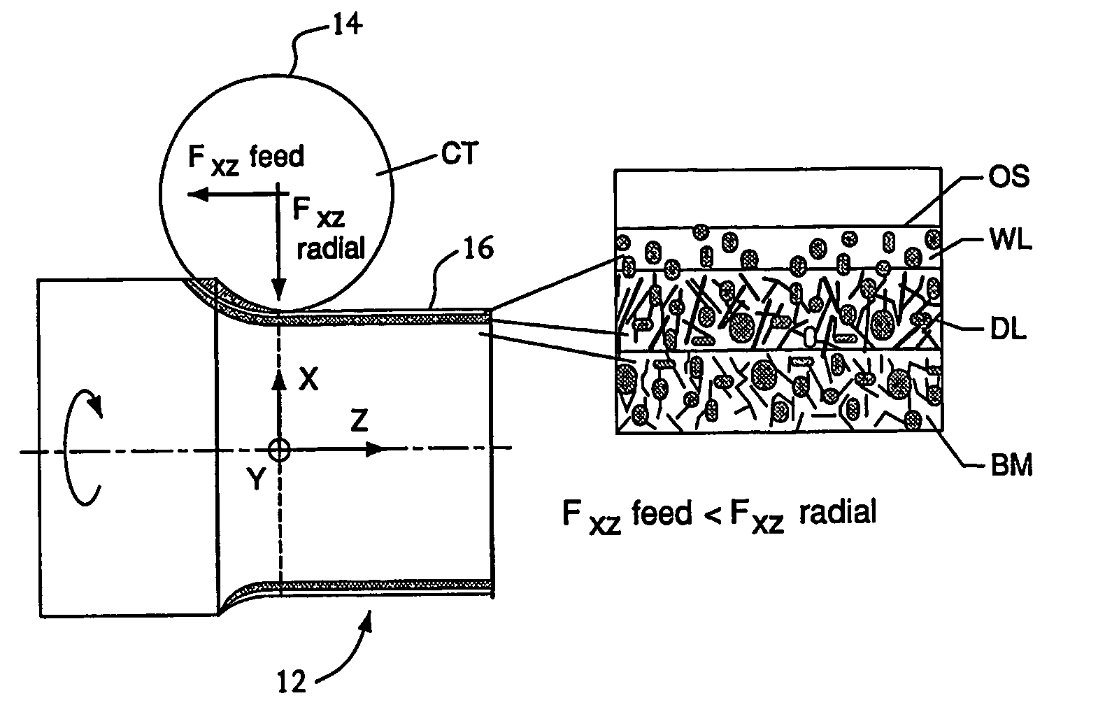
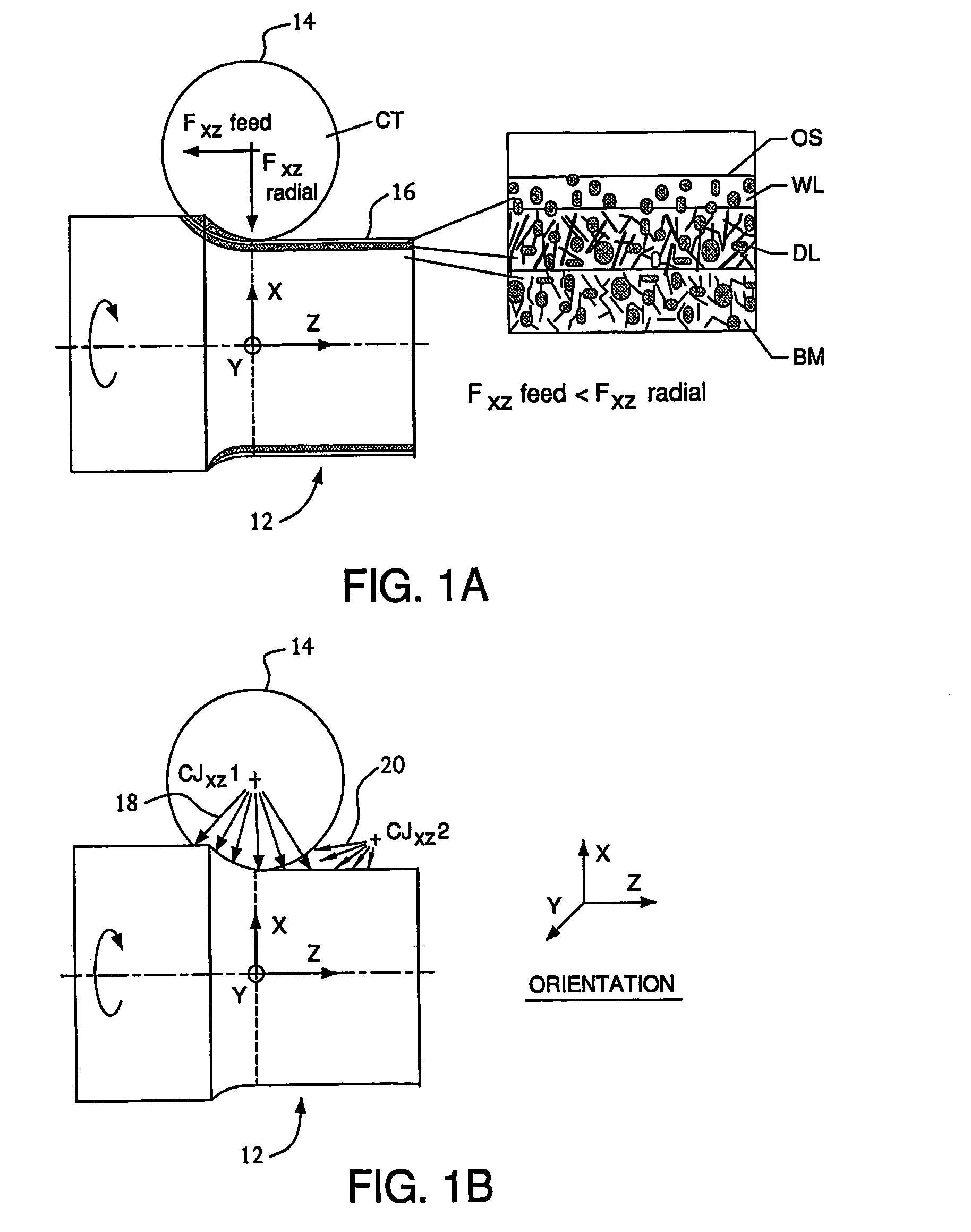
[0050] The present invention involves machining hard metallic workpieces with hard cutting tools using a method which reduces the thickness of, or eliminates, thermomechanically-affected layers, including but not limited to white layer, and allows cutting at higher speeds without an excessive white layer using CBN tool materials, as well as less expensive Al2O3, carbide, cermet, or other hard tool materials. As used hereinafter, the term “white layer” refers to all types of “thermomechanically-affected layers,” including but not limited to those associated with surface tensile stresses (e.g., reduced fatigue-resistance, lower fracture toughness, and / or reduced wear resistance).
[0051] According to the present invention, the thermomechanical load exerted by the cutting tool at the machined surface is reduced using one or a combination of the three techniques (A, B, C) discussed below. [0052] A. Cooling cutting tool with a precisely aimed jet or spray of inert, water-free coolant, so ...
PUM
| Property | Measurement | Unit |
|---|---|---|
| Temperature | aaaaa | aaaaa |
| Temperature | aaaaa | aaaaa |
| Temperature | aaaaa | aaaaa |
Abstract
Description
Claims
Application Information