
Distillation process for reducing the concentration of dinitrogen difluoride and dinitrogen tetrafluoride in nitrogen trifluoride

a technology of dinitrogen and tetrafluoride, which is applied in the direction of distillation regulation/control, separation process, vacuum distillation separation, etc., can solve the problems of less information per device, large line width, and defect rate in the production of high-density integrated circuits

Inactive Publication Date: 2005-01-27
EI DU PONT DE NEMOURS & CO
View PDF5 Cites 6 Cited by
  • Summary
  • Abstract
  • Description
  • Claims
  • Application Information

AI Technical Summary

Benefits of technology

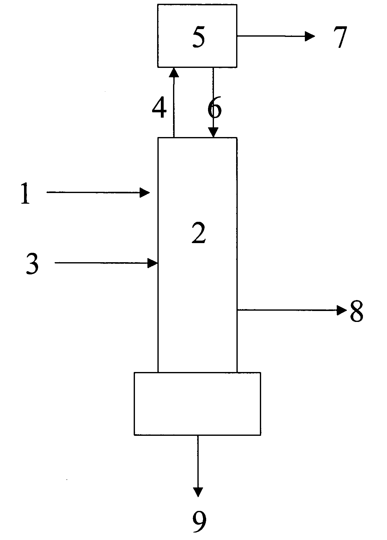
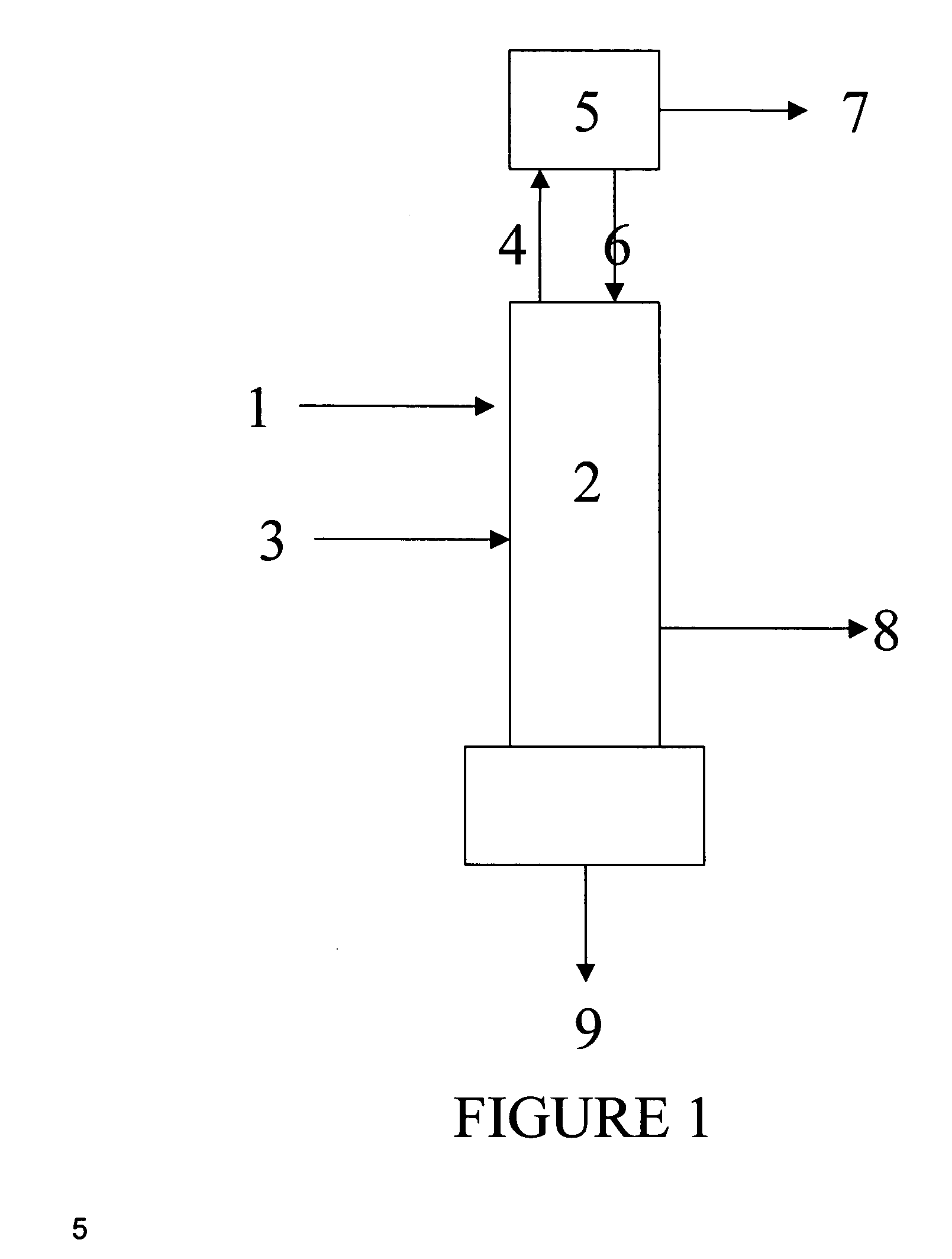
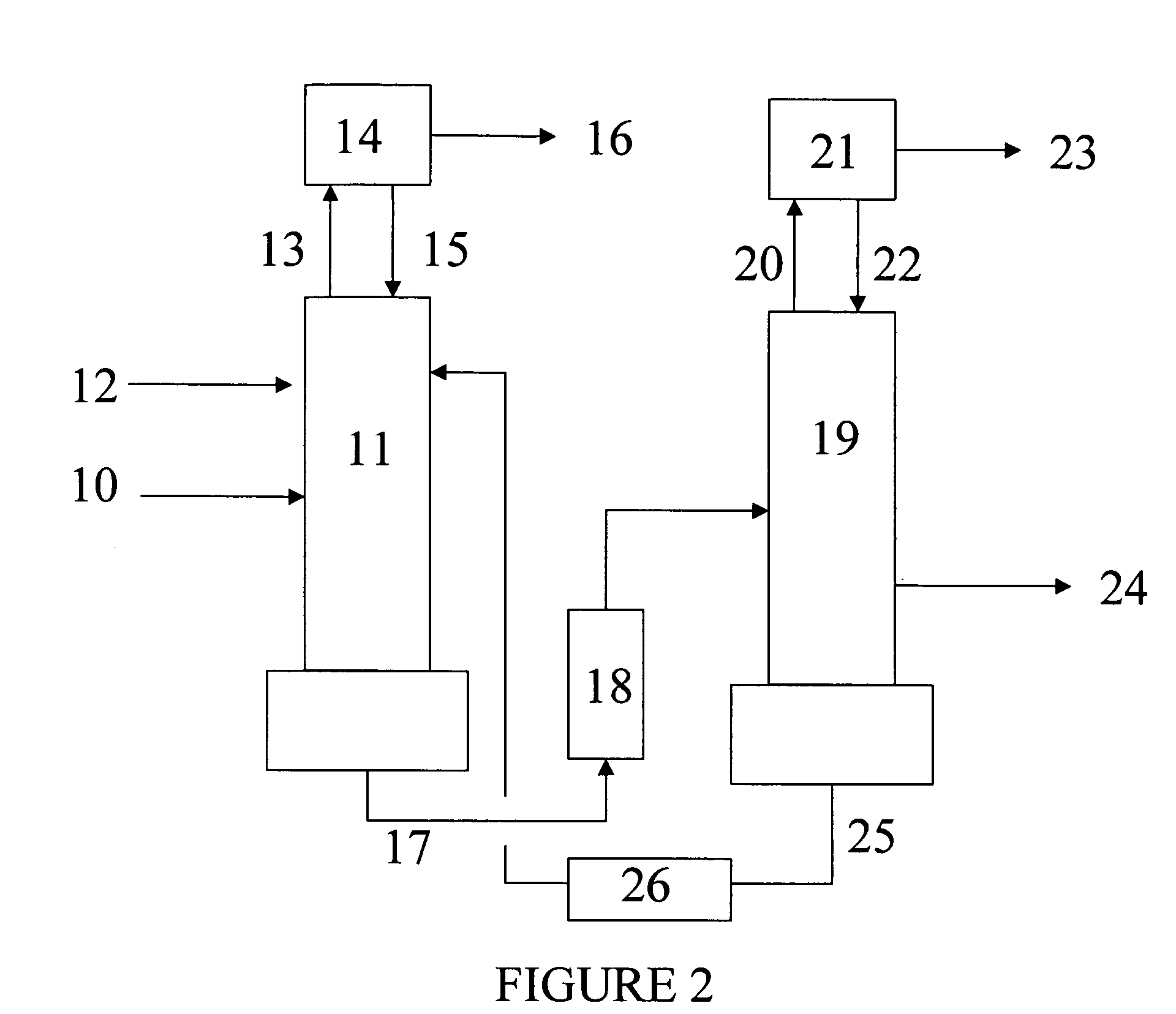
[0018] From the standpoint of reducing said impurities from an NF3 product, it is more economical to reduce said impurities from a stream containing a “higher” concentration rather than from a stream having said impurities at a “lower” concentration. By removing and treating a sidestream in which these impurities have been concentrated, known thermal and adsorptive purification processes for separating N2F2 and N2F4 from NF3 can be applied to smaller volumes of process material and the associated equipment can in turn be smaller and will operate more efficiently. In addition, larger amounts of NF3 substantially free of impurities may be obtained as a product of the distillation.

Problems solved by technology

It is known that even very small amounts of impurities in these gases that enter semiconductor device manufacturing tools can result in wide line width and thus less information per device.
Moreover, the presence of these impurities, including but not limited to particulates, metals, moisture, and other halocarbons in the plasma etchant or cleaning gases, even when only present in the part-per-million level, increases the defect rate in the production of these high-density integrated circuits.
Dinitrogen difluoride and dinitrogen tetrafluoride are particularly undesirable impurities in a nitrogen trifluoride electronic gas product.
Under certain conditions and at relatively low concentration, these compounds can form unstable and even explosive compositions.

Method used


Image

  • Distillation process for reducing the concentration of dinitrogen difluoride and dinitrogen tetrafluoride in nitrogen trifluoride
  • Distillation process for reducing the concentration of dinitrogen difluoride and dinitrogen tetrafluoride in nitrogen trifluoride
  • Distillation process for reducing the concentration of dinitrogen difluoride and dinitrogen tetrafluoride in nitrogen trifluoride

Examples


example 1

[0036] This example is identical to comparative example 1, with the exception that a 4 pph sidedraw is removed from the distillation column at stage 35. The results of this distillation are shown in Table 3.

TABLE 3CASE NUMBER789# of Stages424242Crude Feed Stage303030Vapor Side-Draw Stage353535Column Top Temperature (° C.)−75−75−75Reflux Temperature (° C.)−75−75−75Distillate Temperature (° C.)−75−75−75Bottoms Temperature (° C.)−8−10−17Crude NF3 Feed Temperature (° C.)−60−60−60Top Pressure (psia)214.7214.7214.7Condenser Pressure (psia)214.7214.7214.7Bottoms Pressure (psia)216.7216.7216.7Overhead Takeoff Rate (PPH)96.1195.3893.26Reflux Rate (PPH)2000.002000.002000.00Bottoms Takeoff Rate (PPH)49.8950.6252.74Vapor Sidedraw Rate (PPH)4.004.004.00Crude NF3 FeedNF3 (PPH)99.7099.7099.70F116 (PPH)50.0050.0050.00N2F2-c (PPH)0.100.100.10N2F2-t (PPH)0.100.100.10N2F4 (PPH)0.100.100.10Overhead TakeoffNF3 (PPH)96.1195.3893.26N2F2-c (PPH)0.000000.000000.00000N2F2-t (PPH)0.000000.000000.00000Overhe...

example 2

[0040] This Example is identical to comparative example 3, except that there is now a 10 pph sided raw and the number of stages has been increased from 42 to 62. The results of this distillation may be seen in Table 5.

TABLE 5CASE NUMBER131415# of Stages626262Crude Feed Stage454545Vapor Side-Draw Stage505050Column Top Temperature (° C.)−75−75−75Reflux Temperature (° C.)−75−75−75Distillate Temperature (° C.)−75−75−75Bottoms Temperature (° C.)−8−8−8Crude NF3 Feed−60−60−60Temperature (° C.)Top Pressure (psia)215215215Condenser Pressure (psia)215215215Bottoms Pressure (psia)217217217Overhead Takeoff Rate (PPH)98.8694.5389.98Reflux Rate (PPH)5000.005000.005000.00Bottoms Takeoff Rate (PPH)4991.144995.475000.02Vapor Sidedraw Rate (PPH)10.0010.0010.00Crude NF3 FeedNF3 (PPH)99.7099.7099.70F116 (PPH)5000.005000.005000.00N2F2-c (PPH)0.100.100.10N2F2-t (PPH)0.100.100.10N2F4 (PPH)0.100.100.10Overhead TakeoffNF3 (PPH)98.8600094.5300089.98000N2F2-c (PPH)0.000000.000000.00000N2F2-t (PPH)0.000000.0...

example 3

[0044] This example is identical to case numbers 16 through 20 of comparative example 4, except that there is now a 4 pph sidedraw. The results of this distillation may be seen in Table 7.

TABLE 7CASE NUMBER2122232425High BoilerPFC-116HCFC-22HFC-23HFC-32HFC-125# of Stages4242424242Crude Feed Stage3030303030Vapor Sidedraw Stage3535353535Column Top Temperature (° C.)−75−75−75−75−75Reflux Temperature (° C.)−75−75−75−75−75Distillate Temperature (° C.)−75−75−75−75−75Bottoms Temperature (° C.)−837−181927Crude Feed Temperature (° C.)−60−60−60−60−60Top Pressure (psia)215215215215215Condenser Pressure (psia)215215215215215Bottoms Pressure (psia)217217217217217Overhead Takeoff Rate (PPH)96.1195.8095.9895.8295.81Reflux Rate (PPH)2000.002000.002000.002000.002000.00Bottoms Takeoff Rate (PPH)49.8950.2050.0250.1850.19Vapor Sidedraw Rate (PPH)4.004.004.004.004.00Crude NF3 FeedNF3 (PPH)99.7099.7099.7099.7099.70High Boiler (PPH)50.0050.0050.0050.000.10N2F2-c (PPH)0.100.100.100.100.10N2F2-t (PPH)0.10...


PUM


Abstract

Disclosed is a distillation process for reducing the concentration of impurities dinitrogen difluoride and dinitrogen tetrafluoride in nitrogen trifluoride. The process comprises: (a) distilling a mixture comprising nitrogen trifluoride and dinitrogen difluoride and / or dinitrogen tetrafluoride in a distillation column in the presence of a compound having a higher normal boiling point than nitrogen trifluoride; (b) removing a mixture comprising dinitrogen difluoride and / or dinitrogen tetrafluoride as a sidedraw from the distillation column; (c) removing a mixture comprising the compound having a higher normal boiling point than nitrogen trifluoride from the bottom of the distillation column; and (d) removing a nitrogen trifluoride product having reduced concentration of dinitrogen difluoride and / or dinitrogen tetrafluoride from the top of the distillation column.

Description

CROSS REFERENCE TO RELATED APPLICATIONS [0001] This application claims the priority benefit of U.S. provisional patent application 60 / 462,756, filed Apr. 14, 2003.BACKGROUND OF THE INVENTION [0002] 1. Field of the Invention [0003] The present invention relates to a distillation process for reducing the concentration of the impurities dinitrogen difluoride and dinitrogen tetrafluoride in nitrogen trifluoride. The process involves distilling the nitrogen trifluoride in the presence of a compound with a higher normal boiling point than nitrogen trifluoride and removing as a distillation column overhead stream nitrogen trifluoride substantially free of said impurities, removing as a distillation column sidedraw a concentrated stream comprising said impurities, and removing as a distillation bottom stream said compound with a higher normal boiling point than nitrogen trifluoride. [0004] 2. Description of Related Art [0005] Various gaseous fluorine-containing compounds are utilized in man...

Claims


Application Information

Patent Timeline
IPC IPC(8): C01B21/083
CPCC01P2006/80C01B21/0837B01D3/34B01D3/42C01B21/083
Inventor MILLER, RALPH NEWTONMAHLER, BARRY ASHER
Owner EI DU PONT DE NEMOURS & CO
Learn More