Laser-plasma hybrid welding method

Inactive Publication Date: 2005-01-27
MTU AERO ENGINES GMBH +1
View PDF5 Cites 7 Cited by
  • Summary
  • Abstract
  • Description
  • Claims
  • Application Information

AI Technical Summary

Benefits of technology

Moreover, on account of the electrode-free laser-plasma hybrid welding, the introduction of undesired electrode material into the weld metal is avoided. Furthermore, a disruption-free, unmanned and automated welding process is possible without worn parts having to be constantly replaced.
A further advantage of the laser-plasma hybrid welding process according to the invention is that the heat-affected zone of the plasma jet on the work piece is significantly reduced, which leads to a lower introduction of heat, a reduced work piece distortion and a drop in the levels of damage to the material. Moreover, the laser-plasma hybrid welding process according to the invention allows defect-free welding in terms of reduced weld undercuts and a low porosity in the weld seam.
T

Problems solved by technology

The known processes have proven to have the drawback that the welding speed is relatively low on account of the current intensity being limited by the service life of the electrode, leading to a limited arc power.
This results in further drawbacks with regard to a high thermal load on the work piece, leading to considerable distortion of the work piece.
A further drawback is the restricted use of process gases.
The use of oxygen, for example, and other process gases which

Method used


Image

  • Laser-plasma hybrid welding method
  • Laser-plasma hybrid welding method
  • Laser-plasma hybrid welding method

Examples


first embodiment

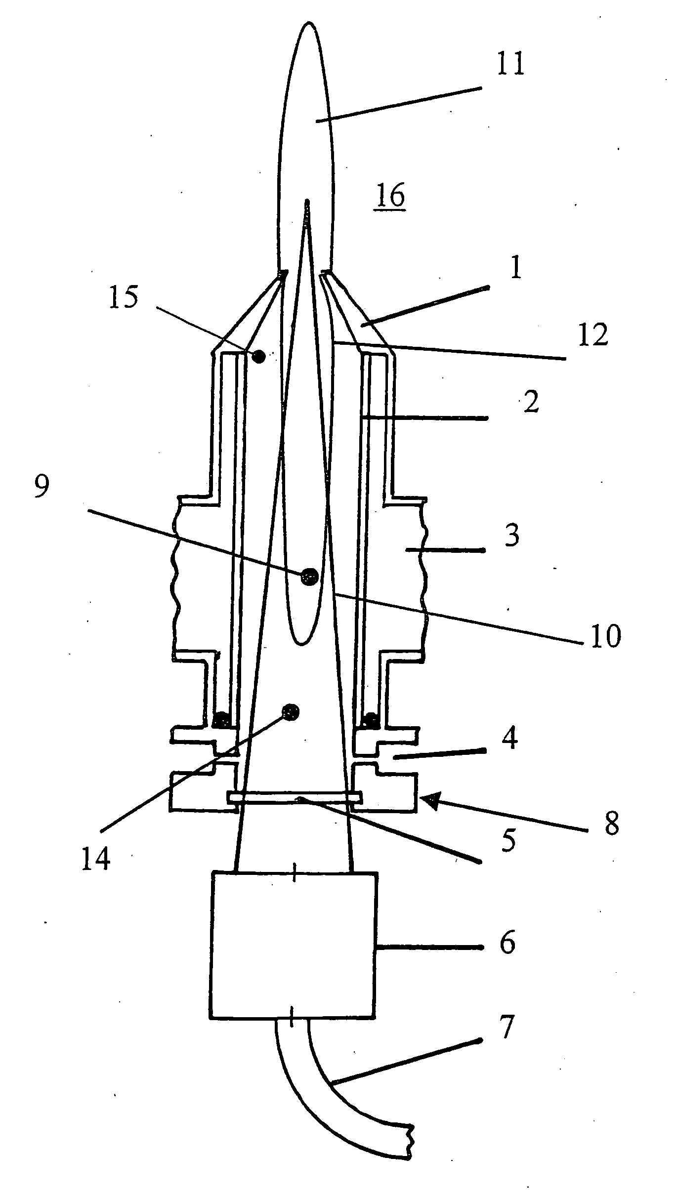
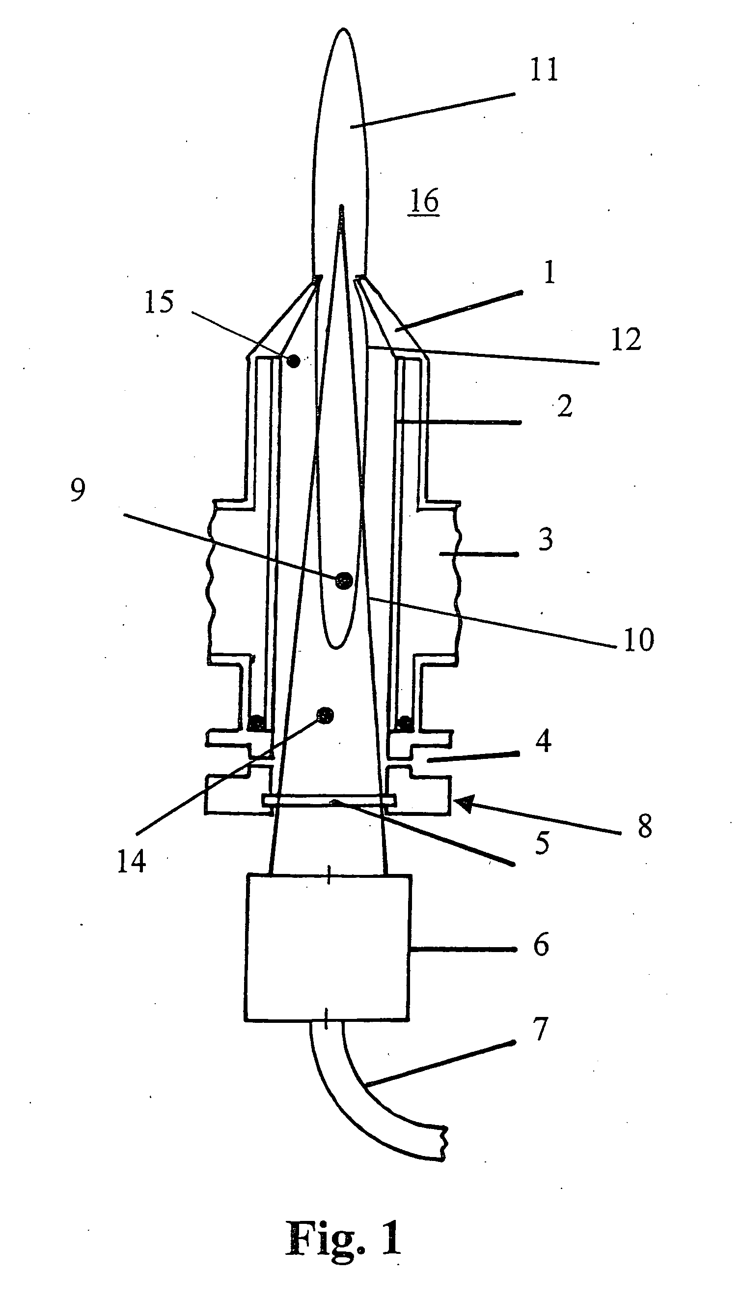
FIG. 1 shows a sectional illustration of a first embodiment for carrying out the process according to the invention. In this embodiment, the laser beam 10 runs through the microwave-transparent tube 2. The illustration shows a microwave-transparent tube 2 which is guided perpendicularly through a hollow waveguide 3 which transports the microwaves generated by a microwave source (not shown). In this case, commercially available waveguides can be used as hollow waveguide 3. However, it is also possible to use hollow waveguides which have a narrowing in the cross section in the region in which the microwave-transparent tube 2 runs through the hollow waveguide 3.

The microwave-transparent tube 2 has a gas inlet opening 14 for the process gas and a gas outlet opening 15 for the plasma 12. The plasma 12 is generated by microwave absorption in the region 9 in which the microwave-transparent tube 2 runs through the hollow waveguide 3.

At the gas inlet opening 14, the microwave-transparent ...

second embodiment

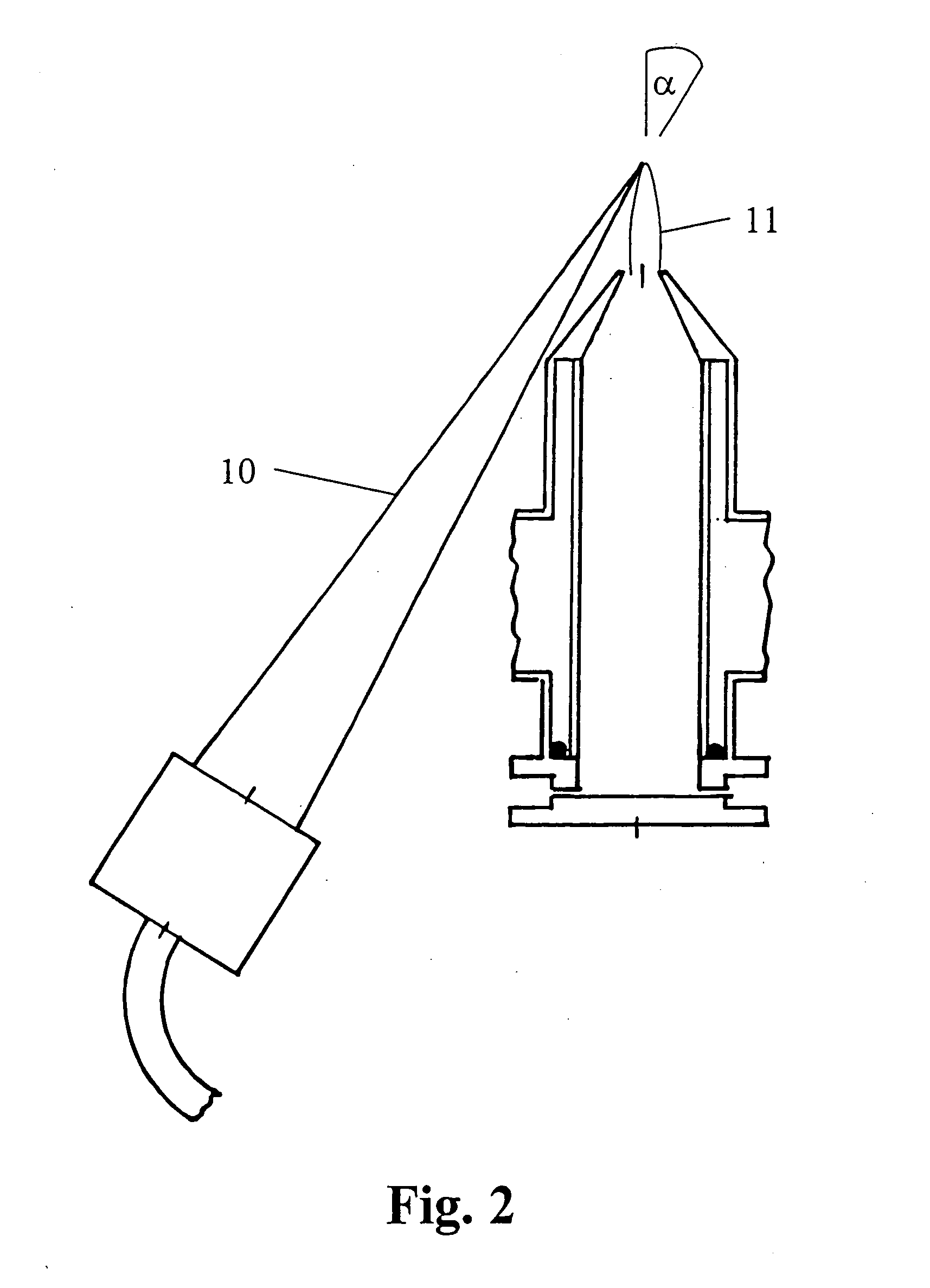
FIG. 2 shows a sectional illustration of a second embodiment for carrying out the process according to the invention. In this embodiment, the laser beam 10 runs outside the microwave-transparent tube 2. The laser beam 10 and the plasma jet 11 are in this case arranged at an angle to one another which is such that they are brought together downstream of the nozzle 1, as seen in the direction of propagation of the plasma jet. The plasma jet 11 and the laser beam 10 are generated as described in FIG. 1.


PUM

PropertyMeasurementUnit
Frequencyaaaaaaaaaa
Frequencyaaaaaaaaaa
Angleaaaaaaaaaa

Abstract

The invention relates to a process for laser-plasma hybrid welding, in which, to weld work pieces, a laser beam (10) and a plasma jet (11) are brought together in the process region close to the work piece. According to the invention, the free microwave-induced plasma jet (11) is generated by means of the following process steps: generation of microwaves in a high-frequency microwave source,
    • guiding of the microwaves in a hollow waveguide (1)
    • introduction of a process gas into a microwave-transparent tube (2), which comprises a gas inlet opening (14) and a gas outlet opening (15), at a pressure p≧1 bar, the process gas being introduced into the microwave-transparent tube (2) through the gas inlet opening (14) in such a manner that it has a tangential flow component,
    • generation of a plasma (12) in the microwave-transparent tube (2) by means of electrode-free ignition of the process gas,
    • generation of a plasma jet (11) by introduction of the plasma (12) into the working space (16) through a metallic nozzle (1) arranged at the gas outlet opening (15) of the tube (2).

Description

BACKGROUND AND SUMMARY OF THE INVENTION The invention relates to a process for laser-plasma hybrid welding. U.S. Pat. No. 6,034,343 describes a fixture in which a laser welding process and a conventional plasma welding process, for example tungsten inert gas welding (TIG) or metal active gas welding (MAG), are combined with one another. In this case, an arc burns between a non-melting electrode, usually a tungsten electrode, and the work piece, with the work piece being partially melted. The laser beam is focused onto the work piece by means of a lens system. The lens system and the electrode are arranged concentrically with respect to one another. The laser beam can then be used to concentrate a high energy output in a narrow and deep area of the partially melted work piece. A further process for the welding of work pieces by means of laser-plasma hybrid welding is described in German publication DE 195 00 512 A1. In this case, the laser beam used to weld the work pieces and the...

Claims


Application Information

Patent Timeline
IPC IPC(8): B23K10/02B23K26/14B23K28/02H05H1/30
CPCB23K10/02B23K26/1429H05H1/30B23K28/02B23K26/348
Inventor BAYER, ERWINHOESCHELE, JOERGSTEINWANDEL, JUERGENWILLNEFF, RAINER
Owner MTU AERO ENGINES GMBH
Why Eureka
Try Eureka