X-ray detector and method for producing x-ray detector

a detector and detector layer technology, applied in the field of x-ray detectors, can solve the problems of inability to obtain thermal stability and the like easily, the resolution characteristic of x-ray diagnostic systems is generally inferior to the direct conversion system, and the scintillator layer decreases, so as to achieve high hardness and binding energy, degradation of luminance, and degradation of luminous efficiency

Inactive Publication Date: 2005-01-27
KK TOSHIBA
View PDF6 Cites 35 Cited by
  • Summary
  • Abstract
  • Description
  • Claims
  • Application Information

AI Technical Summary

Benefits of technology

[0011] Therefore, the present invention provides an X-ray detector of an indirect conversion system having a partition for suppressing degradation in resolution characteristics between pixels, wherein a decrease in brightness because of the existence of the partition is reduced as much as possible.
[0012] The present invention also provides a method for producing the X-ray detector, wherein the structure of the partition and the scintillator layer for reducing a decrease in brightness as small as possible is formed with good homogeneity and reliability.
[0013] The X-ray detector of the present invention has the configuration described below in order to improve the sensitivity characteristic while maintaining high resolution characteristics of the X-ray detector of the indirect system having a partition formed between pixels.

Problems solved by technology

And, there is also a disadvantage that photoconductive material having a low dark current characteristic, a high sensitivity characteristic, thermal stability and the like cannot be obtained easily.
But, it has a disadvantage that its resolution characteristic for X-ray diagnostic systems is generally inferior to the direct conversion system because fluorescent light converted by the scintillator layer causes diffusion or scattering before reaching the photoelectric converting element.
But, the partition of the conventional X-ray detector is formed of metal or the like and not contributing to the X-ray sensitivity.
Therefore, it has a problem that a total light emission amount of the scintillator layer decreases by a portion replaced from the scintillator layer to the partition, and the sensitivity of the X-ray detector deteriorates.

Method used


Image

  • X-ray detector and method for producing x-ray detector
  • X-ray detector and method for producing x-ray detector
  • X-ray detector and method for producing x-ray detector

Examples


Embodiment Construction

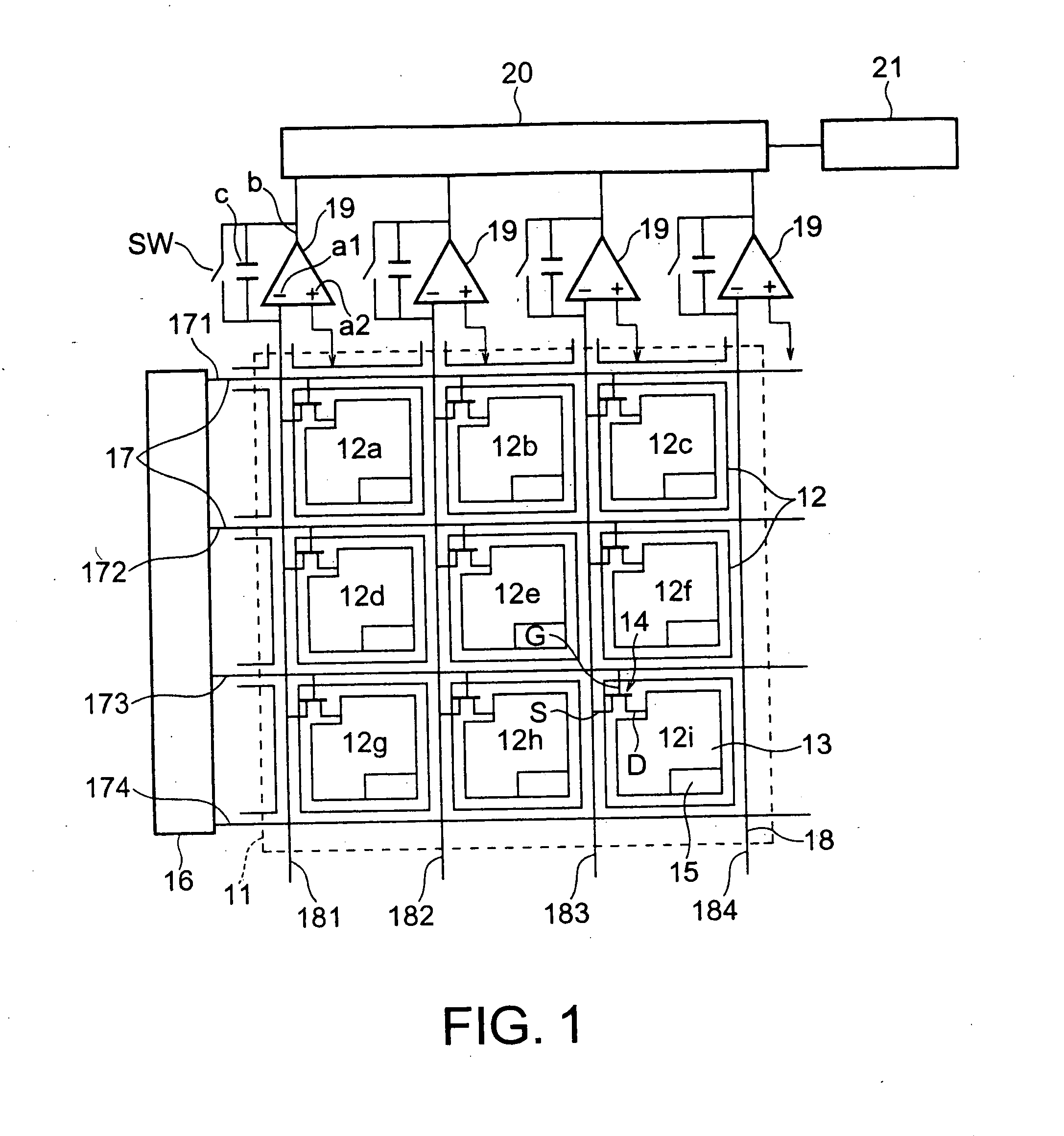
[0041] An embodiment of the present invention will be described with reference to the circuitry diagram of FIG. 1.

[0042] Reference numeral 11 is an X-ray photoelectric converting section, and the X-ray photoelectric converting section 11 is comprised of plural pixel units 12 arranged in matrix. For example, the plural pixel units 12 having the same configuration are two-dimensionally arranged on an insulation substrate such as glass in a row direction (e.g., a horizontal direction in the drawing) and a column direction (e.g., a vertical direction on the drawing). FIG. 1 shows nine pixel units 12a to 12i as an example.

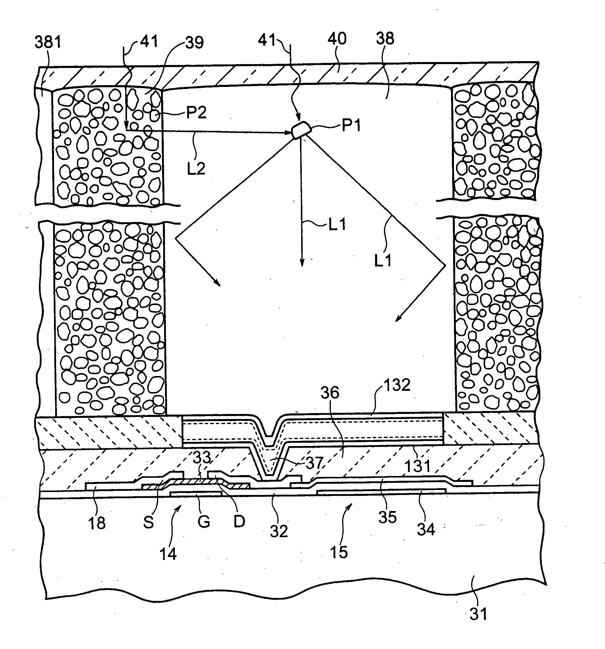
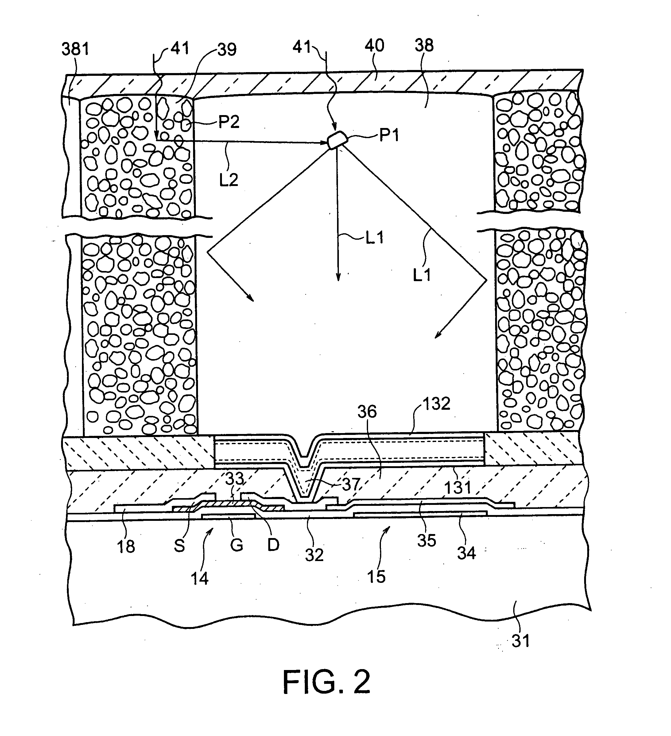
[0043] One pixel unit, e.g., the pixel unit 12i, is comprised of a photodiode 13 for converting light into electric charge, a thin-film transistor (hereinafter referred to as TFT) 14 configuring a switching section, and an electric charge storage section for storing electric charge, such as a storage capacitor 15. The TFT 14 has a gate electrode G, a source electrode ...


PUM


Abstract

An X-ray detector comprising a scintillator layer (38) provided for each pixel and adapted for converting X radiation into light, a storage capacitor (15) for storing, as electric charge, the light converted in the scintillator layer (38), and a partition layer (39) partitioning the adjoining scintillator layers (38) provided to the respective pixels. The scintillator layer (38) contains a fluorescent material (I), the partition layer contains a second phosphor (P2) having optical characteristics different from those of the fluorescent material (IP1). The wavelength of the fluorescent light emitted from the second phosphor (P2) includes a component which is equal to or longer than the shortest wavelength of the fluorescent light emitted from the fluorescent material (IP1).

Description

TECHNICAL FIELD [0001] The present invention relates to an X-ray detector used for detection of X-rays and a method for producing it. BACKGROUND ART [0002] Recently, a flat-type X-ray detector using active matrix is attracting attention as a new-generation X-ray detector for diagnosis. The flat-type X-ray detector is configured to output an X-ray image formed by X-rays or a real-time X-ray fluoroscopic image as a digital signal. [0003] The flat-type X-ray detector is a solid detector, so that it is highly expected in terms of the improvement and stability of performance. [0004] The flat-type X-ray detector for general radiography and chest radiography to collect static images with a relatively large radiation dose has been developed and become commercially available. It is also possible to detect real-time X-ray dynamic images of 30 frames or more per second with a relatively small dose for fluoroscopy. Therefore, products applied to the field of diagnosis of circulatory organs and ...

Claims


Application Information

Patent Timeline
Patent Type & Authority Applications(United States)
IPC IPC(8): G01T1/20G01T1/24
CPCG01T1/2018G01T1/20183G01T1/20
Inventor HOMMA, KATSUHISAAIDA, HIROSHIITO, KENICHIFUJISAWA, AKIKOONIHASHI, HIROSHI
Owner KK TOSHIBA
Why Eureka
Try Eureka