
System and method for mitigating fading of a signal at a radio receiver

Inactive Publication Date: 2005-01-27
WI LAN INC
View PDF5 Cites 14 Cited by
  • Summary
  • Abstract
  • Description
  • Claims
  • Application Information

AI Technical Summary

Benefits of technology

[0009] It is an object of the present invention to provide a novel system and method to mitigate fading and / or other poor reception characteristics of a radio signal experienced at a receiver which obviates or mitigates at least some of the above-identified disadvantages of the prior art.
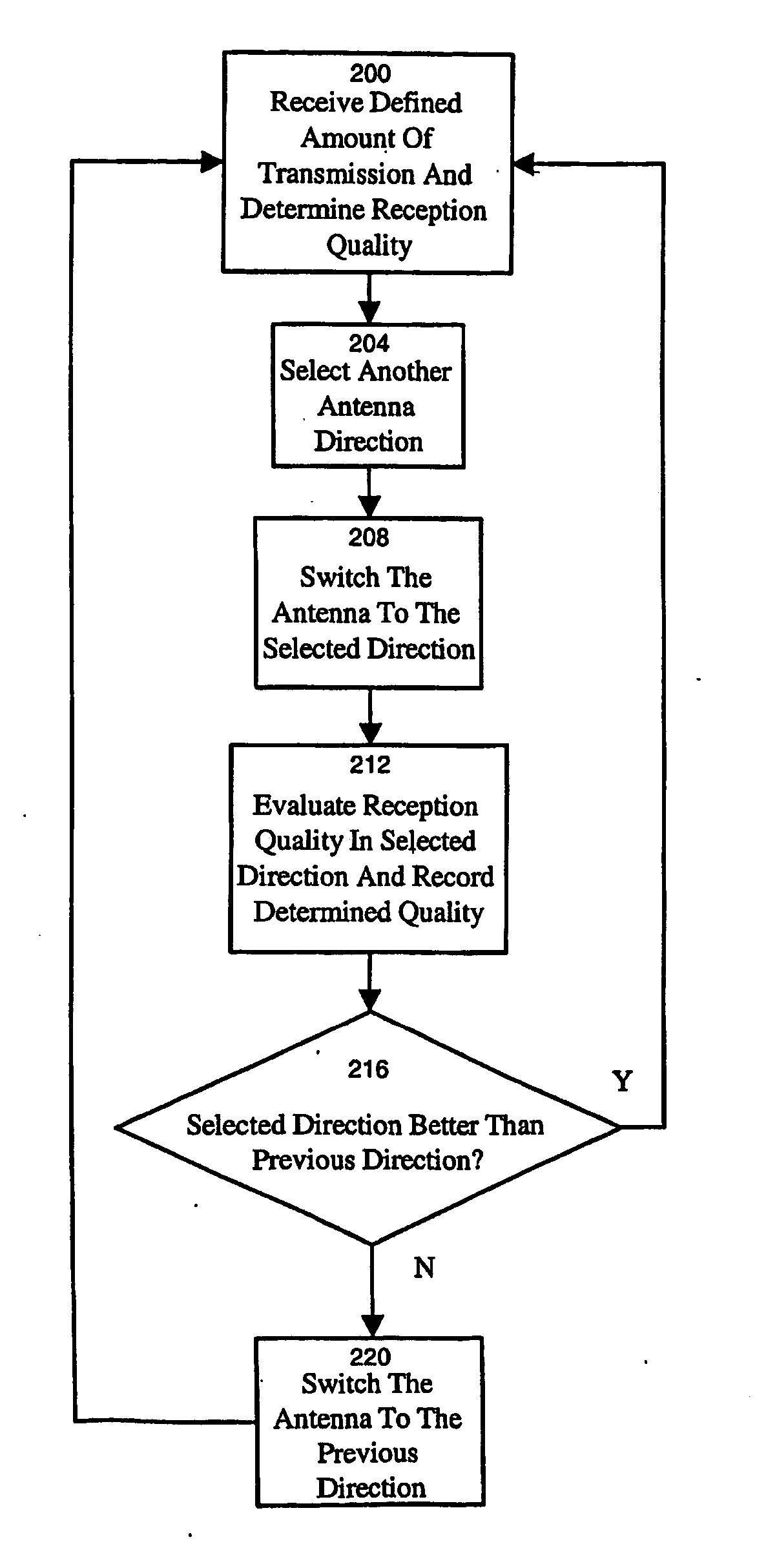
[0034] The present invention provides a method and system for mitigating fading and / or poor reception at a receiver. The receiver includes an antenna diversity mechanism which can be operated in a variety of antenna configurations each of which can provide different reception characteristics. The receiver evaluates the reception quality of the radio signal with the antenna in a first configuration and with the antenna in at least a second configuration and selects the antenna configuration that has the best evaluated reception for use until a subsequent iteration when the process is repeated. The antenna configurations can correspond to configurations wherein reception is favored in different directions or to configurations wherein different antennas are selected, each antenna being spaced from each other antenna.

Problems solved by technology

It is well known that radio signals can suffer from a variety of influences that result in a radio receiver experiencing fading of the received radio signal.
Rayleigh fading, and other multi-path fading effects, result when multipath versions of a signal destructively interfere to attenuate the signal arriving at a receiver.
Such fading is a significant problem in communications system, especially mobile systems where movement of the receiver and changes in the environment both contribute to changing multipath signals.
While such techniques allow system designers to provide a selected probability of reception of a signal, this is achieved at a cost of reduced system throughput, as redundant information must be transmitted, reducing the bandwidth utilization efficiency of the transmission.
One problem with the 3GPP compressed mode is that radio transmission capacity is wasted whenever the empty slots are transmitted.
Another problem with 3GPP compressed mode is that latency is increased during compressed mode as data which would otherwise be transmitted in the empty slots,is delayed until a subsequent frame.
Yet another problem with the 3GPP compressed mode is that it requires coordination between the transmitter and the receiver and this adds delay and overhead servicing requirements to the communication system.
Thus, there will always be some additional delay in how quickly a receiver can evaluate its reception of other transmitters when it is experiencing a fade, or other poor reception characteristics, from the transmitter it is presently receiving.
Also, compressed mode is only employed once poor reception is being experienced and it is not used proactively, to prevent unacceptable reception from occurring, where possible.

Method used


Image

  • System and method for mitigating fading of a signal at a radio receiver
  • System and method for mitigating fading of a signal at a radio receiver
  • System and method for mitigating fading of a signal at a radio receiver

Examples


Embodiment Construction

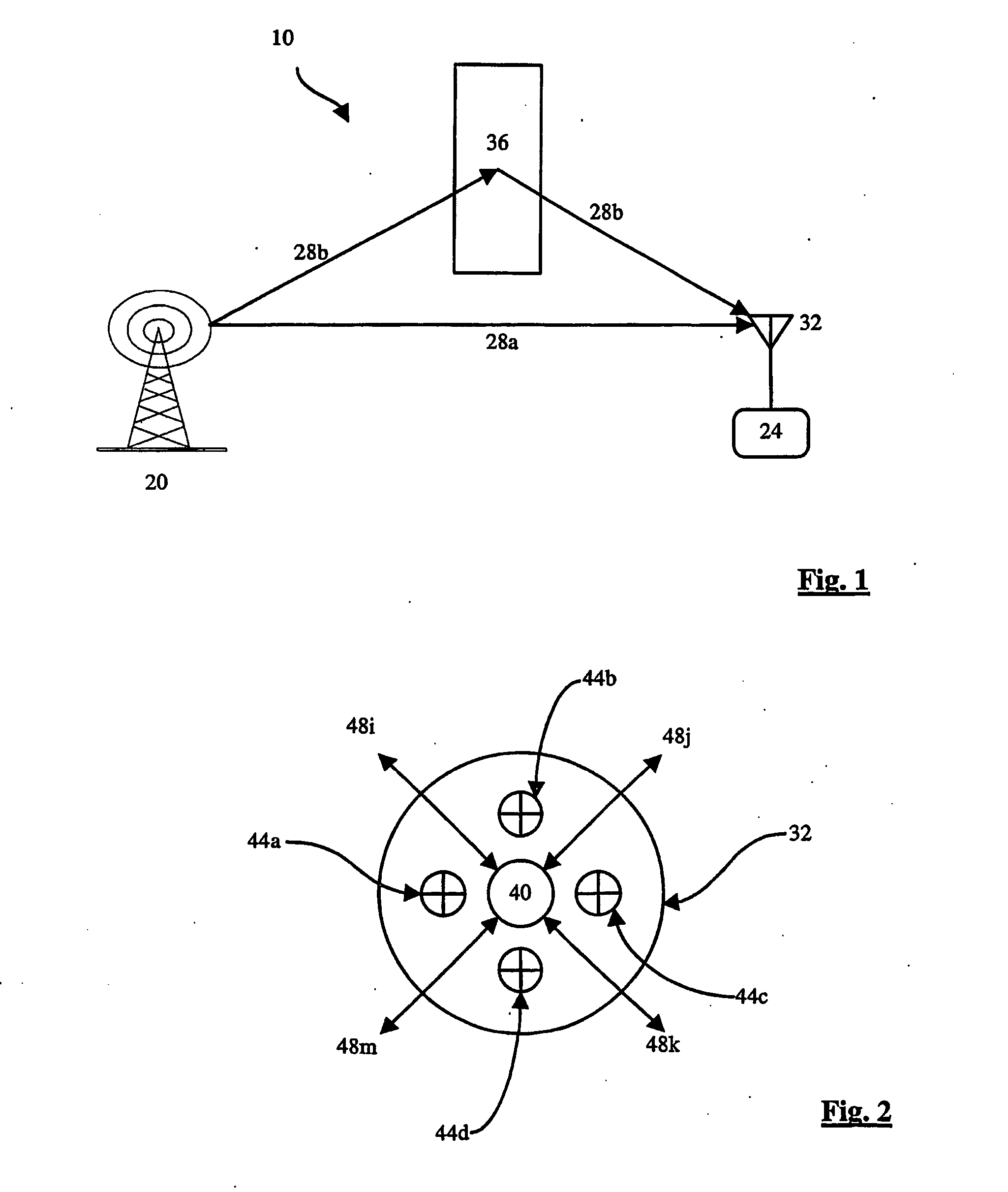
[0043]FIG. 1 shows a communications network 10, such as a wireless local loop system, including a first transceiver, such as base station 20 and a second transceiver, such as subscriber station 24, which are communicating by a radio signal 28 in accordance with an embodiment of the present invention. As is known, radio signal 28 typically travels over many signal paths 28 (for clarity only two signal paths 28a and 28b are shown in the Figure) before being received at an antenna diversity mechanism of subscriber station 24. As shown in the Figure, signal path 28b is a greater distance, the signal having been reflected off of an object 36 such as a building, than signal path 28a which is a direct path. If the present invention was not employed, a fade could be experienced at subscriber station 24 when the signals arriving over paths 28a and 28b, etc., tend to cancel each other at subscriber station 24 through destructive interference.

[0044]FIG. 2 shows an embodiment of antenna divers...


PUM


Abstract

The present invention provides a method and system for mitigating fading and / or poor reception at a receiver. The receiver includes configurations each of which can provide different reception characteristics. The receiver evaluates the reception quality of the radio signal with the antenna in a first configuration and with the antenna in at least a second configuration and selects the antenna configuration that has the best evaluated reception for use until a subsequent iteration, when the process is repeated. The antenna configurations can correspond to configurations wherein reception is favored in different directions or to configurations wherein different antennas are selected, each antenna being spaced from each other antenna. The method can also improve the reception of a signal transmitted by selecting an antenna configuration for transmissions which provides improved reception quality at the destination receiver.

Description

FIELD OF THE INVENTION [0001] The present invention relates to a system and method for mitigating signal fading and / or poor reception experienced at a radio receiver. More specifically, the present invention relates to a system and method to mitigate signal fading and / or poor reception at a receiver by selecting, according to a reception quality, a direction and / or location at which to receive and / or transmit the signal. BACKGROUND OF THE INVENTION [0002] It is well known that radio signals can suffer from a variety of influences that result in a radio receiver experiencing fading of the received radio signal. For example, a radio signal received at a receiver can be subject to Rayleigh fading, other multi-path, or environmental fading influences. [0003] Rayleigh fading, and other multi-path fading effects, result when multipath versions of a signal destructively interfere to attenuate the signal arriving at a receiver. The fading experienced at a receiver typically is unique to tha...

Claims


Application Information

Patent Timeline
IPC IPC(8): H04B7/08H04B7/10H04B1/69H04J13/00
CPCH04B7/0814H04B1/7117
Inventor MANTHA, RAMESHCASTURA, JEFFREY P.
Owner WI LAN INC
Learn More