Communication system

a communication system and communication system technology, applied in the field of communication systems, can solve the problems of inability to transmit hdtv signal corresponding ntsc channels, and inability to go further, so as to achieve the effect of reducing the signal attenuating area and increasing the service area

Inactive Publication Date: 2005-01-27
GK BRIDGE 1
View PDF89 Cites 16 Cited by
  • Summary
  • Abstract
  • Description
  • Claims
  • Application Information

AI Technical Summary

Benefits of technology

More particularly, a receiver capable of demodulation of n-bit data can reproduce n bits from a multiple-bit modulated carrier wave carrying an m-bit data where m>n, thus allowing the communication system to have compatibility and capability of future extension. Also, a multi-level signal transmission will be possible by shifting the signal points of QAM so that a nearest signal point to the origin point of I-axis and Q-axis coordinates is spaced nf from the origin where f is the distance of...

Problems solved by technology

However, the TV broadcast service is a public business and cannot go further without considering the interests and benefits of viewers.
This causes the corresponding NTSC channels to be unavailable during transmission of the HDTV signal.
In any analogue TV broadcast service, there are developed a lot of signal attenuating or shadow regions within its service area due to structural obstacles, geographical inconveniences, ...

Method used


Image

  • Communication system
  • Communication system
  • Communication system

Examples


embodiment 1

One embodiment of the present invention will be described referring to the relevant drawings.

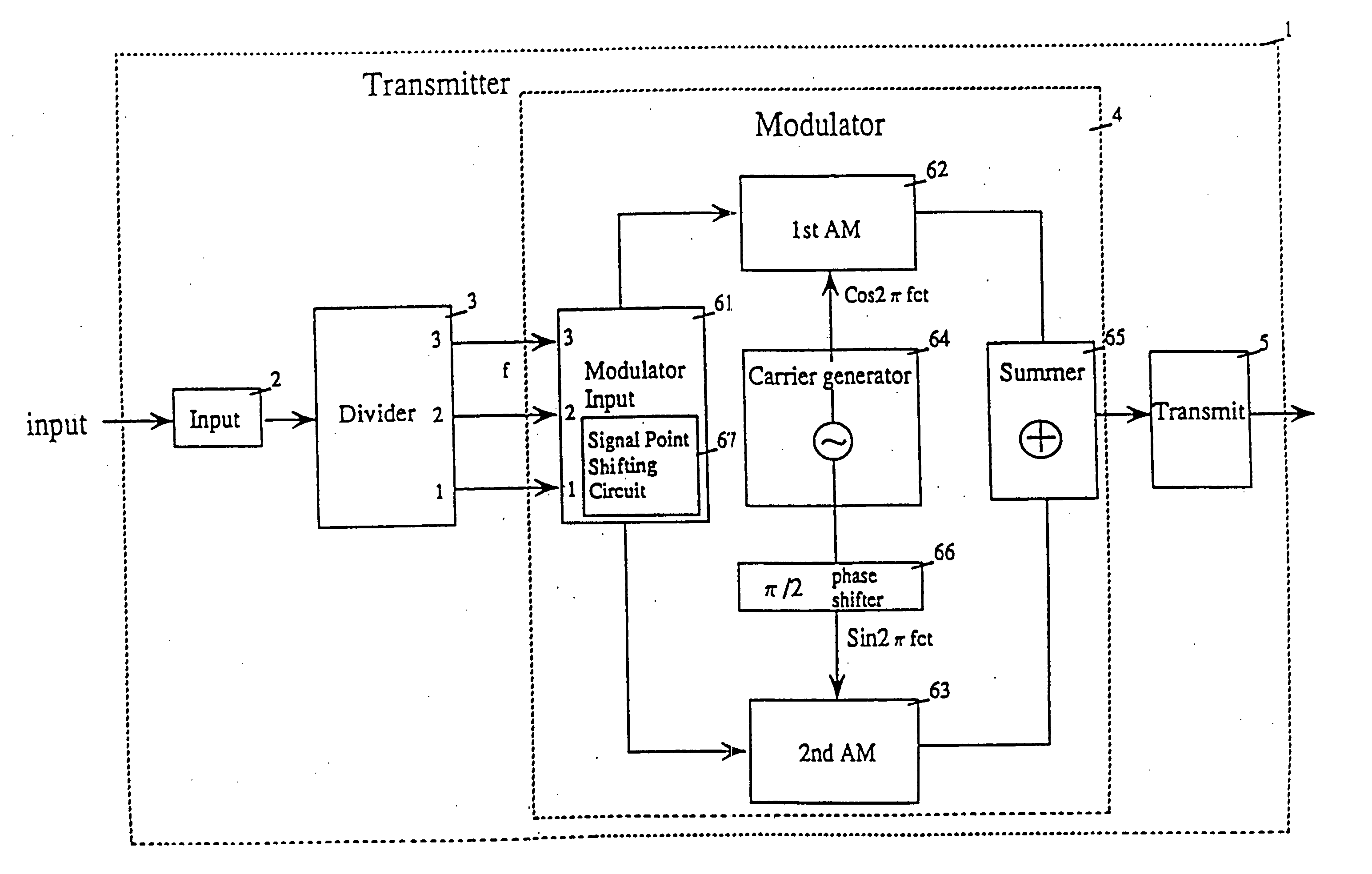
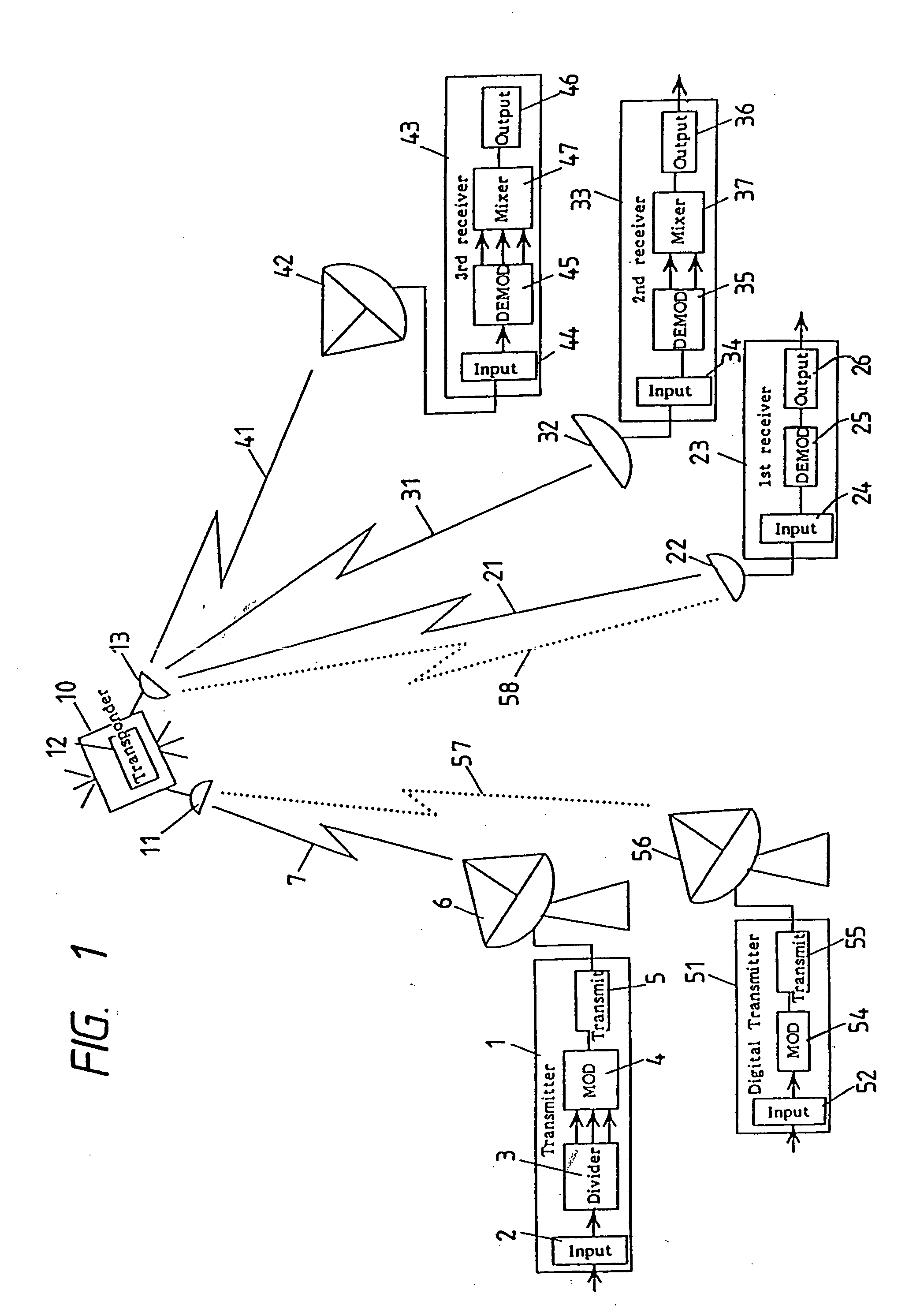
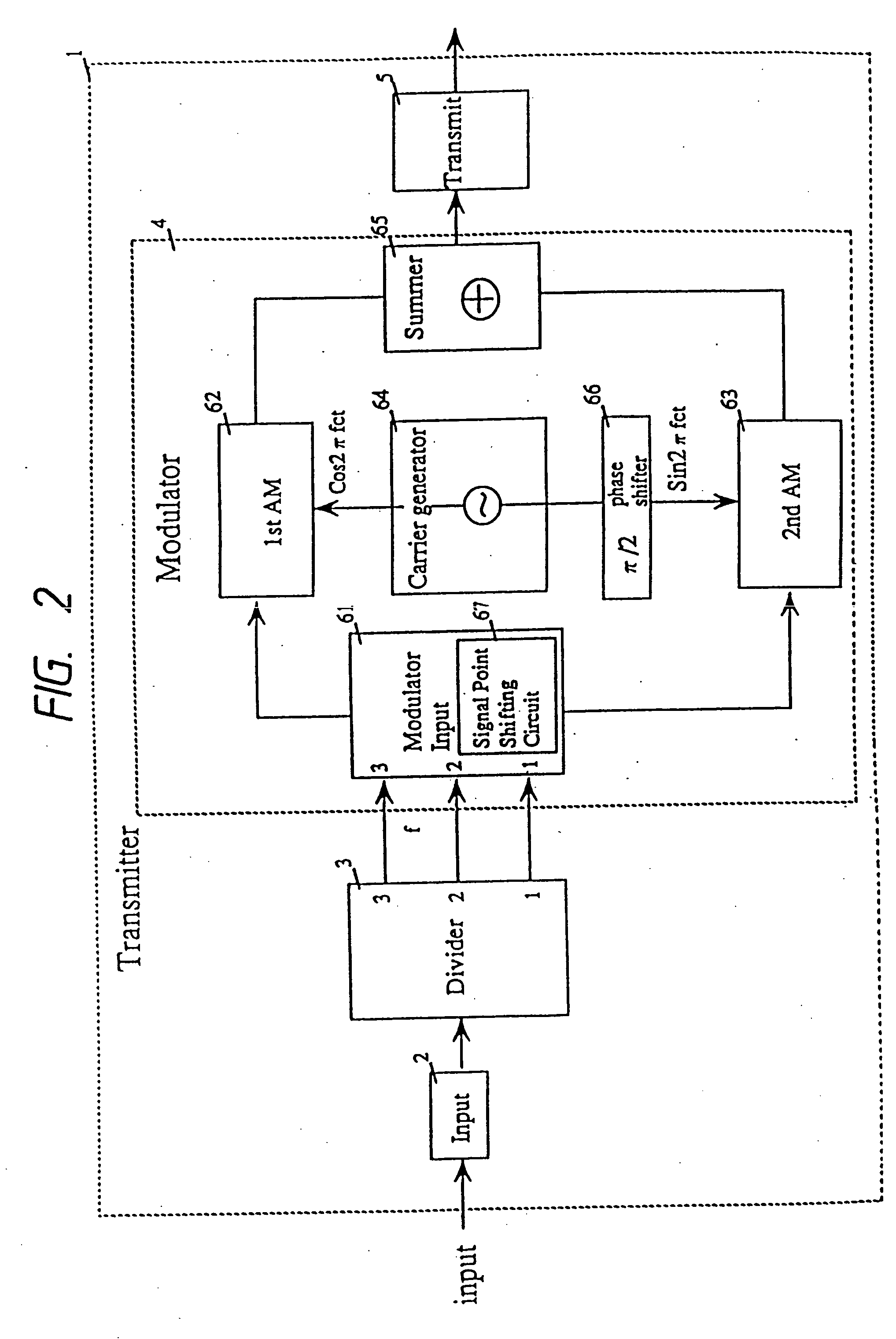
FIG. 1 shows the entire arrangement of a signal transmission system according to the present invention. A transmitter 1 comprises an input unit 2, a divider circuit 3, a modulator 4, and a transmitter unit 5. In action, each input multiplex signal is divided by the divider circuit 3 into three groups, a first data stream D1, a second data stream D2, a third data stream D3, which are then modulated by the modulator 4 before transmitted from the transmitter unit 5. The modulated signal is sent up from an antennal 6 through an uplink 7 to a satellite 10 where it is intercepted by an uplink antenna 11 and amplified by a transponder 12 before transmitted from a downlink antenna 13 towards the ground.

The transmission signal is then sent down through three downlinks 21, 32, and 41 to a first 23, a second 33, and a third receiver 43 respectively. In the first receiver 23, the signal intercepted ...

embodiment 2

A second embodiment of the present invention is featured in which the physical multi-level arrangement of the first embodiment is divided into small levels through e.g. discrimination in error correction capability, thus forming a logic multi-level construction. In the first embodiment, each multi-level channel has different levels in the electric signal amplitude or physical demodulating capability. The second embodiment offers different levels in the logic reproduction capability such as error correction. For example, the data D1 in a multi-level channel is divided into two, D1-1, and D1-2, components and D1-1 is more increased in the error correction capability than D1-2 for discrimination. Accordingly, as the error detection and correction capability is different between D1-1 and D1-2 at demodulation, D1-1 can successfully be reproduced within a given error rate when the C / N level of an original transmitting signal is as low as disenabling the reproduction of D1-2. This will be...

embodiment 3

A third embodiment of the present invention will be described referring to the relevant drawings.

FIG. 29 is a schematic total view illustrating the third embodiment in the form of a digital TV broadcasting system. An input video signal 402 of super high resolution TV image is fed to an input unit 403 of a first video encoder 401. Then, the signal is divided by a divider circuit 404 into three, first, second, and third, data streams which are transmitted to a compressing circuit 405 for data compression before further delivered.

Equally, other three input video signals 406, 407, and 408 are fed to a second 409, a third 410, and a fourth video encoder 411 respectively which all are arranged identical in construction to the first video encoder 401 for data compression.

The four first data streams from their respective encoders 401, 409, 410, 411 are transferred to a first multiplexer 413 of a multiplexer 412 where they are time multiplexed by TDM process to a first data stream mult...


PUM


Abstract

At the transmitter side, carrier waves are modulated according to an input signal for producing relevant signal points in a signal space diagram. The input signal is divided into, two, first and second, data streams. The signal points are divided into signal point groups to which data of the first data stream are assigned. Also, data of the second data stream are assigned to the signal points of each signal point group. A difference in the transmission error rate between first and second data streams is developed by shifting the signal points to other positions in the space diagram. At the receiver side, the first and/or second data streams can be reconstructed from a received signal. In TV broadcast service, a TV signal is divided by a transmitter into, low and high, frequency band components which are designated as a first and a second data stream respectively. Upon receiving the TV signal, a receiver can reproduce only the low frequency band component or both the low and high frequency band components, depending on its capability.

Description

BACKGROUND OF THE INVENTION 1. Field of the Invention The present invention relates to a communication system for transmission / reception of a digital signal through modulation of its carrier wave and demodulation of the modulated signal. 2. Description of the Prior Art Digital communication systems have been used in various fields. Particularly, digital video signal transmission techniques have been improved remarkably. Among them is a digital TV signal transmission method. So far, such digital TV signal transmission system are in particular use for e.g. transmission between TV stations. They will soon be utilized for terrestrial and / or satellite broadcast service in every country of the world. The TV broadcast systems including HDTV, PCM music, FAX, and other information service are now demanded to increase desired data in quantity and quality for satisfying millions of sophisticated viewers. In particular, the data has to be increased in a given bandwidth of frequency alloca...

Claims


Application Information

Patent Timeline
IPC IPC(8): G11B5/09H04J11/00H03M13/25H03M13/35H04B14/04H04H20/00H04H20/74H04J1/02H04J3/00H04L1/00H04L27/00H04L27/02H04L27/04H04L27/06H04L27/10H04L27/18H04L27/22H04L27/26H04L27/34H04L27/36H04L27/38H04N5/38H04N5/40H04N5/44H04N5/455H04N5/46H04N5/78H04N5/7826H04N5/92H04N7/015H04N7/04H04N7/045H04N7/06H04N7/08H04N7/081H04N7/20H04N7/24H04N11/04H04N11/24H04N21/2343H04N21/2383H04N21/438H04N21/4402H04N21/442H04N21/4425H04N21/462H04N21/63H04N21/647
CPCH03M13/23H04N21/440272H03M13/256H03M13/2936H03M13/35H03M13/356H03M13/6538H04L1/0041H04L1/0045H04L1/0054H04L1/0057H04L1/0058H04L1/0059H04L1/006H04L1/0065H04L1/007H04L5/0007H04L5/0046H04L27/02H04L27/04H04L27/183H04L27/2602H04L27/2604H04L27/3405H04L27/3488H04L27/36H04L27/38H04L27/3854H04L2001/0098H04L2027/0036H04L2027/0053H04L2027/0067H04N5/4401H04N5/455H04N7/015H04N7/24H04N11/004H04N21/234327H04N21/2383H04N21/4382H04N21/4383H04N21/44209H04N21/4425H04N21/4621H04N21/631H04L27/2627H04L27/2649H04N19/30H04N19/63H04N19/60H04N19/37H03M13/253H04N11/26H04N21/426H04L27/362H04L25/4975
Inventor OSHIMA, MITSUAKI
Owner GK BRIDGE 1
Why Eureka
Try Eureka