Array-based biomolecule analysis

a biomolecule and array technology, applied in the field of biomolecule samples analysis, can solve the problems of existing protein chips, less robust proteins than dna, fragile and denatured, and difficult to lay down antibodies or other protein capture agents, and achieve high density arrays, preserve post-translational modifications, and ensure the effect of stability

Inactive Publication Date: 2005-01-27
SHIMADZU CORP
View PDF17 Cites 6 Cited by
  • Summary
  • Abstract
  • Description
  • Claims
  • Application Information

AI Technical Summary

Benefits of technology

[0030] The principal advantage of the present invention over the prior art is that it generates an array of authentic proteins without the need for surface immobilisation chemistry as is required for existing protein chips. This is important in preserving post-translational modifications of proteins such as glycosylation and phosphorylation. By the methods described herein, antibodies specific to sites that have undergone post-translational modifications can be used to detect differences in phosphorylation that occur with cell differentiation, or in tumour cells compared to normal cells.
[0031] In one feature, the information contained in the image of the primary array can be used to define the type of micro array printed on the primary array. For example, the size of a particular spot to be analysed can be used to determine the pattern and spacing of reagents dispensed onto that spot. For example, an 8×8 array of reagents with 20 micron drops can be printed on a spot having a 200 microns diameter with the reagent spots spaced 25 microns apart, whereas with a larger, say 400 microns spot, the reagent spots may be spaced 50 microns apart. A typical protein spot distribution from a 2D gel can be 500-3000 microns. One model of chemical printer may generate an array of 100 micron droplets with 120 microns center to center. An experiment can be done using a 3×3 array of 100 micron micro-spots in a 500 micron 2D macrospot. A 10×10 array of 100 micron micro-spots easily fits inside a 2000 micron 2D spot.
[0032] Since there is sufficient accuracy in the depositing system it is possible to print very high density arrays onto individual positions of the primary array. With precision fibre optics it should be possible to identify minute interactions (e.g., a 10×10 array of 80 pL drops inside a 1000 micron spot).
[0033] In one particularly preferred feature, it would be an advantage to print multiple proteolytic enzymes as the micro array onto particular protein spots of the macro array. For example, on a 500 micron diameter protein spot a micro array of a number of endoproteinase enzymes (trypsin, endoproteinase LysC, endoproteinase GluC and endoproteinase Asp-N, with the preferred enzymes being trypsin and GluC), is printed in 200 micron size spots spaced 200 microns apart (centre to centre). The spot size and spacing is sufficiently small so that the average MALDI-TOF-MS nitrogen laser beam (100 micron) can be positioned so as to only desorb the analytes of one particular enzyme reaction within a spot of the macro array. The advantage of this feature is that the micro array of proteinases would lead to an increased peptide coverage detected during MALDI-TOF-MS analysis of the protein spot in the macro array.

Problems solved by technology

However, the task of laying down antibodies or other protein capture agents is far from straightforward.
A further problem arises in that proteins are much less robust than DNA and are fragile and will denature if they are treated harshly.
There are major drawbacks with existing protein chips.
As discussed above, this is typically done by using either arrayed antibodies, such as monoclonal antibodies, which are slow and expensive to produce, or using arrayed antigens.
However, the specificity of the bound antigens and of the bound antibodies in particular, is not high.
A second problem is that the use of a single antibody cannot address the issue of a protein having a number of isoforms.
There is a possibility that biologically active isoforms may be swamped by non-active isoforms.
There is a major problem with abundant proteins in a sample causing high background noise by non-specific binding to the array.
Thus, it impossible to be sure that the interaction on the protein chip is anything like a real interaction as would take place between an authentic protein and, for example, another protein.

Method used


Image

  • Array-based biomolecule analysis
  • Array-based biomolecule analysis
  • Array-based biomolecule analysis

Examples


example 1

[0085] The aim of this example was to develop chemical printing technology for micro-dispensing human serum that is either seronegative or seropositive for Mycobacterium tuberculosis (TB) as an approach for defining patient immunoreactivity for TB using a purified TB antigen on a nitrocellulose matrix. It will be appreciated that this approach could be used for defining patient immunoreactivity to a number of conditions or diseases by using appropriate antigens.

[0086] Materials and Methods 1.1

[0087] Human serum isolated from two patients, one seronegative and the other seropositive for TB, was diluted 1 in 10 using PBS, pH 7.4+0.05% (w / v) sodium azide +0.1% (v / v) Tween-20 (PBS wash buffer (PBS-WB)) and then filtered through a 0.22 μm syringe filter (Millipore, Danvers, Mass.). Four microlitres of a 370 μg / ml solution of purified 38 kDa TB antigen in PBS, pH 7.4 were applied onto a nitrocellulose membrane (Bio-Rad, Hercules, Calif.) and then allowed to dry. Non-specific binding sit...

example 2

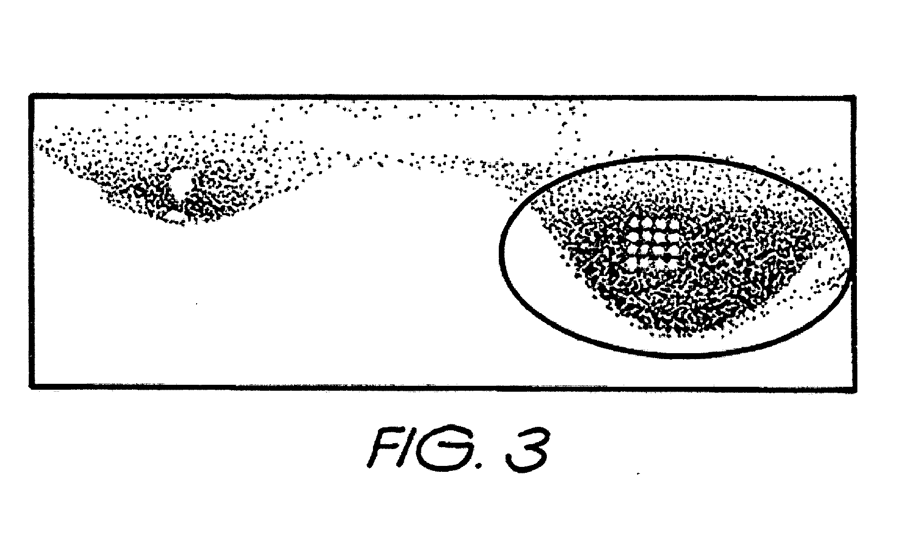
[0091] The development of chemical printing technology for micro-dispensing human serum that is either seronegative or seropositive for Mycobacterium tuberculosis (TB) as an approach for defining patient immunoreactivity for TB using a purified TB antigen subjected to SDS-PAGE and electrotransferrance to nitrocellulose with / without subsequent Direct Blue staining.

[0092] Materials and Methods 2

[0093] 14.8 μg of 38 kDa TB antigen were diluted to 200 μl using ×1 SDS-PAGE non-reducing sample buffer. Sample was then analysed by SDS-PAGE (1.48 μg of antigen per lane) using a 4-12% (w / v) Tris-Bis polyacrylamide gradient gel (Invitrogen, Carlsbad, Calif.) followed by electrotransferrance to nitrocellulose. Two lanes of the blot were visualised using Direct Blue stain (FIG. 3) whilst the other two lanes were not stained. Both blots were allowed to dry at room temperature and were subsequently blocked with 0.5% (w / v) casein in PBS-WB for 15 min. Both blots were then rinsed with PBS-WB and a...

example 3

[0096] This example concerns the application of enzymes to proteins on an array prior to matrix assisted laser desorption ionisation (MALDI) analysis of the fragmented protein in a mass spectrometer. As is known, different enzymes cleave proteins at different amino acid sites. Some enzymes such as LysC, AspN, ArgC cleave at only one specific amino acid site. This is a problem in MALDI analysis as it produces a few large fragments which tends not to produce a very informative spectrum. Other enzymes such as pepsin and chymotrypsin cleave proteins at many amino acid sites. Use of these enzymes prior to MALDI analysis is also problematic as too many small fragments are produced which produces a large number of very small peaks in the spectrum which are very difficult to interpret. Trypsin and GluC cleave at two amino acid sites and this tends to produce good spectra for analysis and thus are the enzymes of choice in MALDI analysis.

[0097] Even so, because these enzymes only cleave at s...


PUM

PropertyMeasurementUnit
diameteraaaaaaaaaa
diameteraaaaaaaaaa
diameteraaaaaaaaaa

Abstract

Separation of macromolecules by one-dimensional or two-dimensional methods, such as gel electrophoresis, produces an array of macromolecules, which can be transferred to a support, thereby producing the same array as on the gel. In the case of one-dimensional gel electrophoresis, because of the regular spacing of the gel lanes and the predictable direction of migration of the macromolecules, the positions of the macromolecule spots or bands in the array can be predicted to be at least within the area of the support corresponding to the lanes of the gel. Where the molecular weight of a macromolecule of interest is known, molecular weight markers can be used to determine where the macromolecule band is on the support, even if the macromolecule is not stained in the gel or on the support. Assays that reveal characteristics of the macromolecule can be carried out by spotting reagents onto the support in a series of microspots of small volume in a line which intersects the macromolecule band, and which corresponds to the line of the direction of migration of the macromolecules on the gel. Appropriate detection methods can be applied, depending on the reagent, to see the results. The steps for locating the bands of macromolecules, applying reagents, and detecting the effect of the reagent on the macromolecule can be automated in an appropriate instrument.

Description

RELATED APPLICATIONS [0001] This application is a continuation-in-part of U.S. application No. 10 / 471,355, filed Jan. 9, 2004 [35 U.S.C. §371(c) date], which is the U.S. National stage of International Application No. PCT / AU01 / 01562, filed 30 Nov. 2001, published in English. This application claims priority under 35 U.S.C. § 119 or 365 to Australia Application No. PR 3780, filed 16 Mar. 2001. The entire teachings of the above applications are incorporated herein by reference.FIELD OF THE INVENTION [0002] This invention relates to the analysis of samples of biomolecules, particularly proteins. BACKGROUND OF THE INVENTION [0003] There has been much discussion in recent literature on the development of a protein chip. Broadly, these are protein arrays (commonly called micro arrays). The current vision is for a protein micro array (in the meaning of the common usage) that will be able to measure thousands of proteins simultaneously, protein-protein interactions, small molecule interacti...

Claims


Application Information

Patent Timeline
Patent Type & Authority Applications(United States)
IPC IPC(8): B01L3/00G01N27/447G01N35/00G01N35/02
CPCB01L3/5085G01N27/44717Y10T436/25G01N35/00029G01N35/028G01N27/44726
Inventor SLOANE, ANDREW J.PLUSKAL, MALCOLM G.GOOLEY, ANDREW A.JOSS, JANICE LEELUDOWYKE, RUSSELL IANHSU, MICHAEL KUNG-HSI
Owner SHIMADZU CORP
Why Eureka
Try Eureka