Multidimensional eye tracking and position measurement system for diagnosis and treatment of the eye

a position measurement and eye tracking technology, applied in the field of improved ophthalmic diagnostic measurement or treatment, can solve problems such as reducing the effectiveness of correction or measurement, and achieve the effects of improving the accuracy of diagnosis and treatment, and fast eye tracking and eye tracking

Active Publication Date: 2005-02-03
SENSOMOTORIC INSTR FUR INNOVATIVE SENSORIK MBH D B A SENSOMOTORIC INSTR
View PDF7 Cites 357 Cited by
  • Summary
  • Abstract
  • Description
  • Claims
  • Application Information

AI Technical Summary

Benefits of technology

[0081] Specifically, the integration of the fast non-image based LADAR tracking system combined with the imaging device based Eye Position Measurement system is proposed to overcome certain limitations of the LADAR tracker, such as the requirement for constant pupil size and providing a method to determine and correct for pupil center shifts due to pupil size changes. The LADAR tracker provides a fast pupil based tracking of the eye using a stabilization device. The Multidimensional Eye Position Measurement Subsystem may observe the eye either through the stabilized mirror or directly along the optical axis and provide a measurement of pupil size and an offset measurement of the pupil center due to pupil size changes by examining other landmarks on the eye with described methods (i.e. limbus features). The pupil size is measured with the imaging device based Eye Position Measurement system and is provided to the LADAR tracker to adjust its spacing of the spots tracked on the pupil / iris boundary. This allows the LADAR tracker to track fast eye movements even with different pupil sizes. Pupil size changes occur only at a lower speed, hence the pupil center shift obtained with the slower imaging device based Eye Position Measurement system is sufficient as a positioning offset to the laser positioning control system to offset the intended ablation position with the pupil center shift during the surgery. Similarly, other enhanced position information such as depth, torsional rotations may be used to correct the laser positioning of the treatment. The stabilized image of LADAR tracker may be used by the Multidimensional Eye Position Measurement Subsystem to image the eye at higher spatial resolution (less field of view is required since the measurement range is extended through the moving mirrors) and reducing the processing effort for several of the described methods. The combination of these systems allows accurate and very fast tracking of the eye with the LADAR tracker independent of pupil size and its change, and further dimensions and security measures provided from the Multidimensional Eye Position Measurement Subsystem.
[0082] A similar combination is proposed by this invention with the CRP trackers, where the image based measuring device provides the absolute orientation measurement relative to the CRP tracker and optionally also selective position to be used by the CRP tracker to track fast movements of the eye. The CRP tracking system provides a fast stabilization of the eye relative to the selected target on the eye.
[0083] Advanced diagnostic and / or treatment methods and procedures, such as Femto-second laser systems for refractive surgeries require a highly accurate distance measurement of the corneal surface relative to the laser device and its thickness at the current treatment location. For this purpose this invention includes—in addition to the eye tracking system—an optional integration of an Optical Coherence Tomography (OCT) system for enhanced depth and thickness measurement. The OCT measurement beam can be embedded coaxially with the optical axis of the diagnostic and / or treatment system and hence positioned with its position device to the intended location on the eye with the offset position of the eye from the eye tracking system. The OCT technique provides a measurement of the distance of the cornea and its thickness at this location on the eye. The diagnostic and / or treatment device may now record the depth and thickness measurement or control for example the focus of a Femto-second laser system to perform an appropriate ablation at the intended depth within the cornea using the distance and thickness information at this location. Repeating this procedure at different locations relative to the eye—stabilized by the eye tracker—provides a diagnostic measurement map without eye motion artifacts (i.e. to measure the thickness of the cornea either before a flap cut, to decide appropriate thickness of the cut or after the cut to determine residual thickness for secure treatments) or enables a secure intra-corneal treatment (i.e. cut a flap). For a stabilized embodiment the OCT beam may be embedded also through the stabilization mirror hence providing a measurement always at a fixed location on the eye.

Problems solved by technology

Foreign objects, such as surgical instruments need to be securely identified to prevent these instruments obstructing the surgical or measuring beam and therefore reducing the effectiveness of the correction or measurement.

Method used


Image

  • Multidimensional eye tracking and position measurement system for diagnosis and treatment of the eye
  • Multidimensional eye tracking and position measurement system for diagnosis and treatment of the eye
  • Multidimensional eye tracking and position measurement system for diagnosis and treatment of the eye

Examples


Embodiment Construction

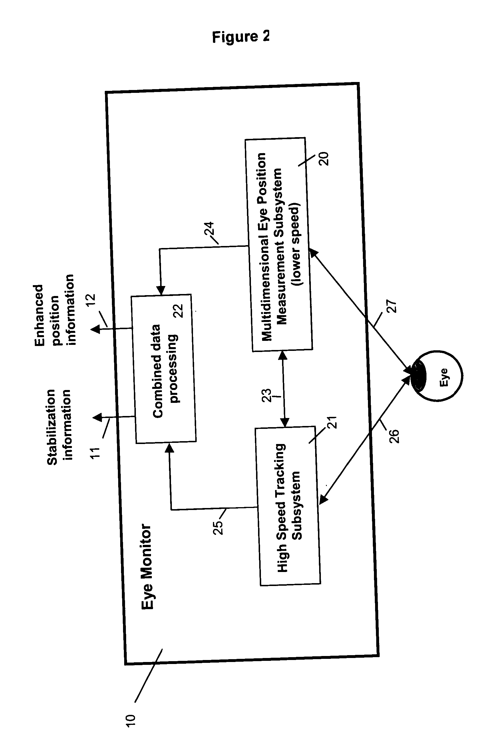
[0084] The general description of the Eye Monitor is described already in the summary of the invention as well as the functional overview of the subsystems of the Eye Monitor. In this section we will now describe first the Eye Position Measurement Subsystem and its overall integration into the Diagnostic and / or Treatment device, followed by the description of High Speed Tracking Subsystems and the joint integration with Eye Position Measurement Subsystem into the into the Diagnostic and / or Treatment device.

[0085] 1 Eye Position Measurement Subsystem

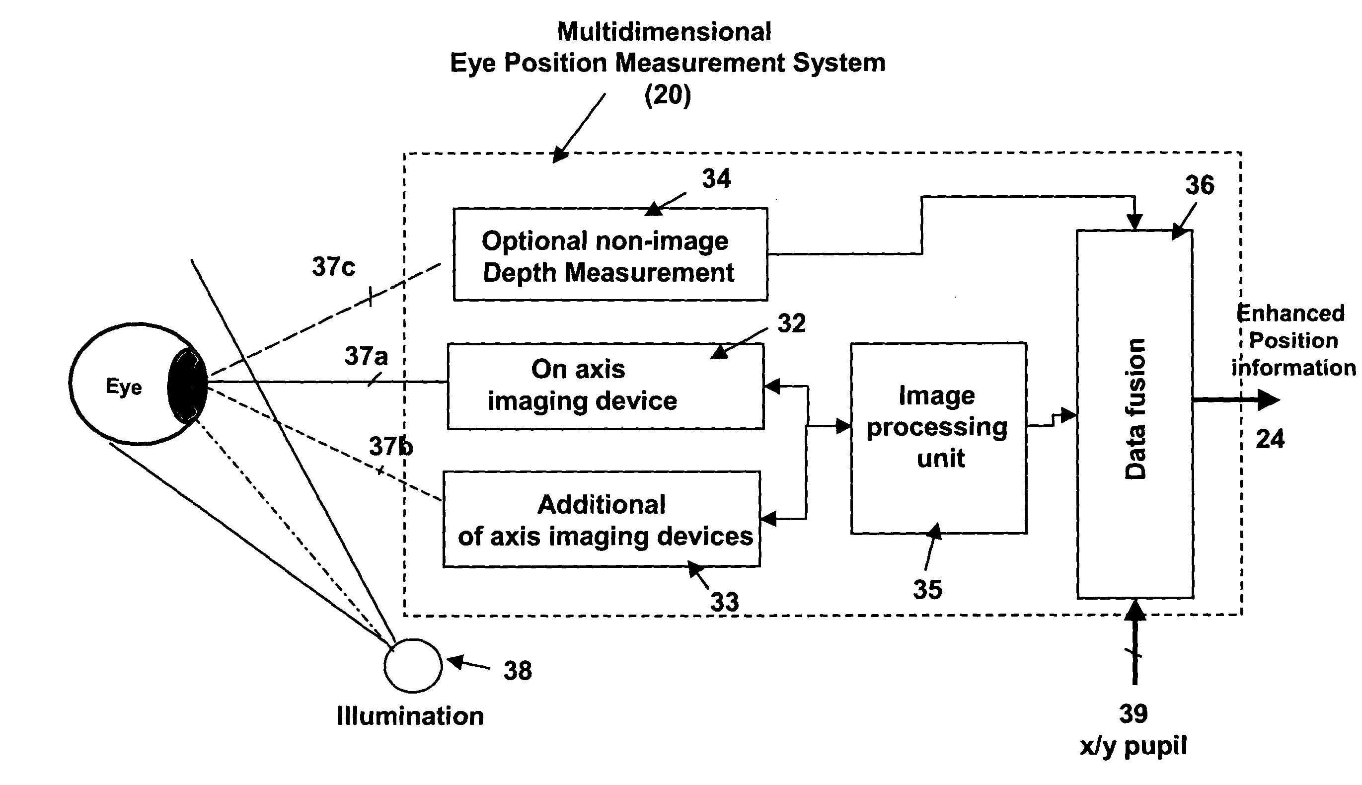
[0086] 1.1 Overview of System Components

[0087] The Eye Position Measurement System is detailed in FIG. 3. It consists of one imaging device 32 (e.g. CCD, CMOS imaging devices) that observes the eye coaxially along the optical axis of the diagnostic and / or treatment device 37a. It provides means to determine various measurements like pupil and non-pupil based horizontal and vertical eye position measurement, torsional eye position (roll...


PUM


Abstract

The present invention relates to improved ophthalmic diagnostic measurement or treatment methods or devices, that make use of a combination of a high speed eye tracking device, measuring fast translation or saccadic motion of the eye, and an eye position measurement device, determining multiple dimensions of eye position or other components of eye, relative to an ophthalmic diagnostic or treatment instrument.

Description

[0001] The present application is a regular patent application of, and claims the benefit of priority from, the following U.S. Provisional patent applications [0002] (1) U.S. Provisional Patent Application Ser. No. 60 / 267,931 filed Feb. 9, 2001 [0003] Method and apparatus for tracking translations and rotations of the eye in 6 dimensions in laser refractive surgery; Huppertz et al., [0004] (2) U.S. Provisional Patent Application Ser. No. 60 / 277,309 filed Mar. 20, 2001 [0005] Method and Apparatus for real time, dynamic measurement of corneal distance and pachymetry using eye tracking and optical coherence tomography; Ralf Weise, Winfried Teiwes, Eberhard Schmidt [0006] (3) U.S. Provisional Patent Application Ser. No. 60 / 350,684 filed Nov. 13, 2001 [0007] Method and apparatus for measuring eye movements and combining it with different eye tracking technologies in order to maintain a fast, robust, accurate, and absolute eye position during treatment or diagnosis of the eye; Teiwes et a...

Claims


Application Information

Patent Timeline
Patent Type & Authority Applications(United States)
IPC IPC(8): A61B3/113A61F9/008A61F9/013
CPCA61B3/113A61F9/008A61F2009/00851A61F9/013A61F2009/00846A61F9/00804
Inventor TEIWES, WINFRIEDGRECU, HORIA
Owner SENSOMOTORIC INSTR FUR INNOVATIVE SENSORIK MBH D B A SENSOMOTORIC INSTR
Why Eureka
Try Eureka