Tarnish deterring tin coating

a technology of tin coating and tin coating, which is applied in the field of tin coating, can solve the problems of reducing the performance of electrical devices, reducing the wettability of solder, and affecting the performance of soldering, and achieve the effect of preventing tarnishing of the coated substra

Inactive Publication Date: 2005-02-03
WIELAND ROLLED PROD NORTH AMERICA LLC
View PDF3 Cites 10 Cited by
  • Summary
  • Abstract
  • Description
  • Claims
  • Application Information

AI Technical Summary

Benefits of technology

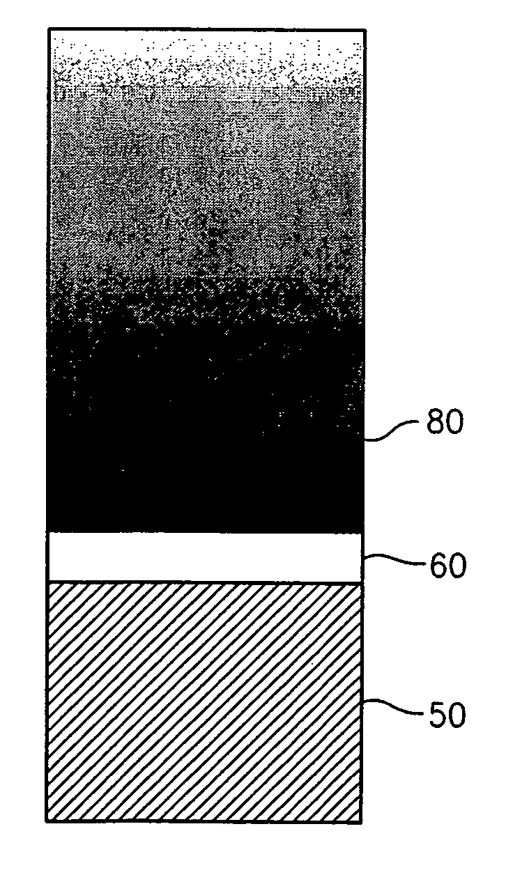
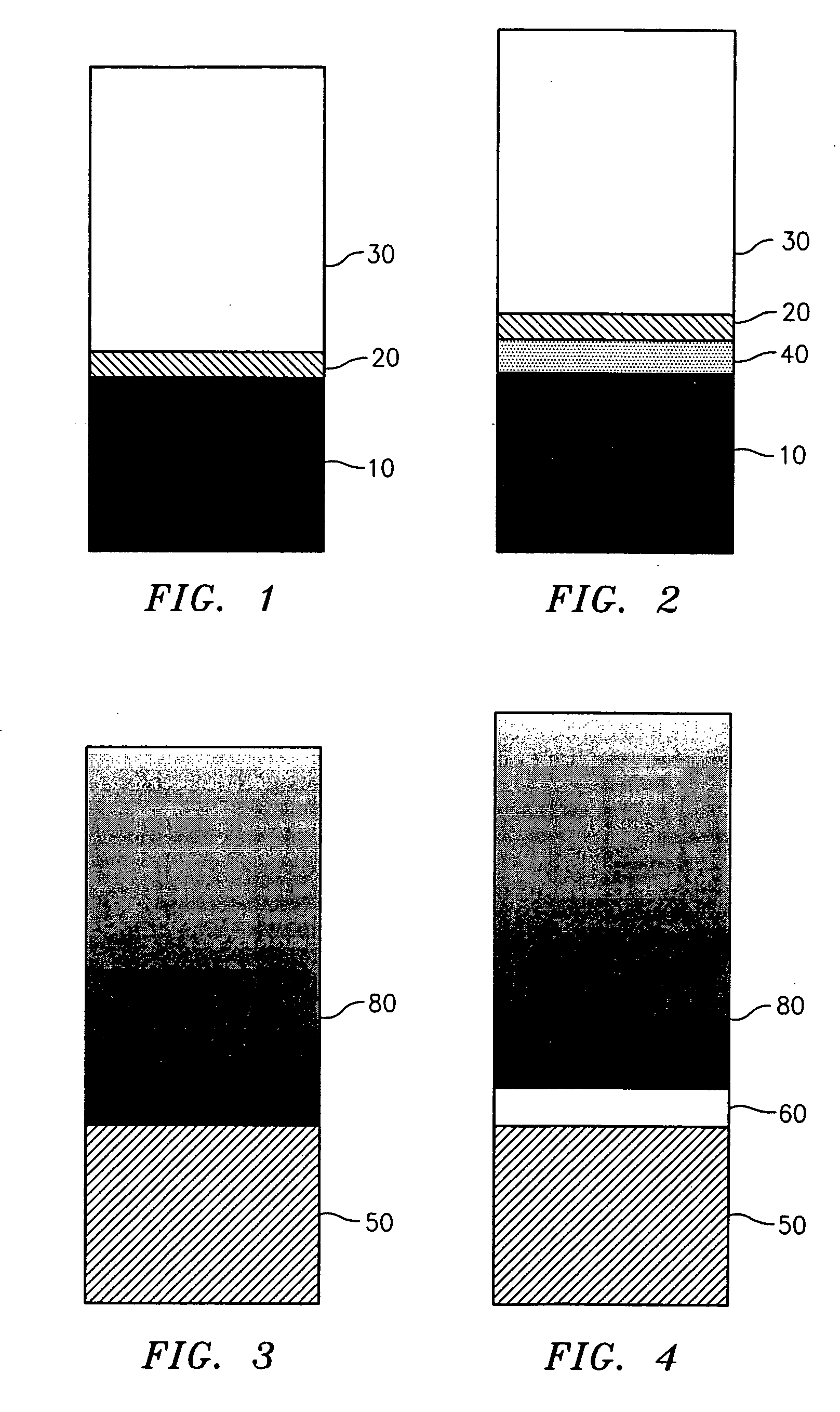
In one aspect, the present invention is directed to a coated substrate, comprising: an antitarnish layer deposited on a substrate in an amount effective to prevent tarnishing of the coated substrate; and an outer layer deposited onto the antitarnish layer, the outer layer comprising tin or tin alloys having at least 50% by weight tin.

Problems solved by technology

Oxidation and tarnishing of electrical contact surfaces generally results in high electrical contact resistance, thereby reducing performance of electrical devices.
In addition, oxidation and tarnishing of electrical contact surfaces reduces the wettability of solder, and generally makes soldering problematic.
However, under certain conditions (e.g., elevated temperatures in air or other oxygen containing atmospheres), tin coatings have a tendency to oxidize and produce a yellowish oxide film that discolors the surface of the tin coating.
Although the oxide film is typically only about 50-200 Angstroms in thickness, the surface of the tin may turn a distinct yellow color, which is undesirable to many consumers.
In addition, under certain conditions (e.g., elevated temperature environments), the oxidation layer may attain a thickness that degrades the contact resistance of a coated electrical terminal.
Although this article recognizes the need to prevent oxidation of tin, it does not disclose an efficient method to introduce oxide resisting elements into the tin coating such that these elements have an increased concentration at the surface of the tin that is exposed to ambient air.
This reference also fails to disclose an efficient method for applying selected oxide resistant elements into a surface of a tin layer exposed to ambient air.

Method used


Image

  • Tarnish deterring tin coating
  • Tarnish deterring tin coating
  • Tarnish deterring tin coating

Examples


examples

The following examples are intended to illustrate, but in no way limit the scope of the present invention. All parts and percentages are by weight and all temperatures are in degrees Celsius unless explicitly stated otherwise.

Deposition of Antitarnish Layers

The general steps for depositing the coating compositions of the present invention are as follows:

A selected substrate is first electrocleaned to remove oils and other contaminants from the substrate surface. A sodium hydroxide-based or other alkaline cleaner is used in an anodic cleaning process to clean the substrate surface. The electrocleaning process usually works most efficiently at 20-55° C. with a current density range of 10-50 asf. The substrate is then rinsed clean with DI water. The substrate then undergoes an activation step where the surface is exposed to a sulfuric acid dip. After another DI water rinse, the antitarnish layer is deposited onto the substrate using techniques known in the art as discussed herei...


PUM

PropertyMeasurementUnit
thicknessaaaaaaaaaa
thicknessaaaaaaaaaa
thicknessaaaaaaaaaa

Abstract

The present invention is directed to a coated substrate, comprising: an antitarnish layer deposited on a substrate in an amount effective to prevent tarnishing of said coated substrate; and an outer layer deposited onto said antitarnish layer, said outer layer comprising tin or tin alloys having at least 50% by weight tin. The present invention is also directed to coated substrates having a concentration gradient of antitarnish agent diffused into the coating, as well as methods of forming such coated substrates.

Description

BACKGROUND OF THE INVENTION 1. Field of the Invention The invention relates to tin coatings that resist tarnishing and discoloration, and more particularly to a coating made from an antitarnish layer and a tin-base layer deposited over the antitarnish layer. The layers may be combined to form a gradient of antitarnish agent within the tin-base layer. The invention also relates to methods of making the above coatings. 2. Background of the Invention Oxidation and tarnishing of electrical contact surfaces generally results in high electrical contact resistance, thereby reducing performance of electrical devices. In addition, oxidation and tarnishing of electrical contact surfaces reduces the wettability of solder, and generally makes soldering problematic. Therefore, compositions and methods to reduce oxidation and tarnishing of electrical contacts have been pursued in the art. One method to reduce oxidation or tarnishing of electrical contacts, and particularly copper or copper a...

Claims


Application Information

Patent Timeline
Patent Type & Authority Applications(United States)
IPC IPC(8): B32B15/04B32B15/08B32B15/18B32B15/20H05K3/24
CPCC23C30/00H05K3/244Y10T428/12694Y10T428/12722Y10T428/12715Y10T428/12792Y10T428/12458Y10T428/12576Y10T428/265Y10T428/12569Y10T428/12708Y10T428/26Y10T428/12903Y10T428/31678
Inventor LAURELLO, CHRISTOPHER P.TYLER, DEREK E.CHEN, SZUCHAINFISTER, JULIUS C.
Owner WIELAND ROLLED PROD NORTH AMERICA LLC
Why Eureka
Try Eureka