Fuel cell

a fuel cell and separator technology, applied in the field of fuel cells, can solve the problems of difficult application of the fuel cell system to portable electronic equipment, inability to downsize, and prolong the residence time of the anode and the cathode, and achieve the effect of facilitating molding and reducing the weight of the separator

Inactive Publication Date: 2005-02-03
PANASONIC CORP
View PDF7 Cites 20 Cited by
  • Summary
  • Abstract
  • Description
  • Claims
  • Application Information

AI Technical Summary

Benefits of technology

[0015] Further, a fuel cell system with a high power generation output can be obtained by including a plurality of fuel cell bodies for use in the system. However, simply using a plurality of independent fuel cell bodies increases power consumption of auxiliary equipment required by individual fuel cells to generate electric power, leading to upsizing of the entire system.
[0096] According to the twenty-fourth aspect of the present invention, the cathode is provided with a cathode-side separator made of a nonconductive material, so that if a resin material is used as the nonconductive material for example, it becomes possible to decrease the weight of the separator and facilitate molding thereof, thereby achieving mass production of a complicated groove shape in addition to the effect of the first aspect.

Problems solved by technology

However, in the fuel cell formed with this separator, the grooves formed on the surface of the separator serve as fuel and oxygen passageways so that the residence time in the anode and the cathode is prolonged, though a high pressure is required to let them flow.
In such a case, downsizing of the fuel cell system is not feasible, making it difficult to apply the fuel cell system to the portable electronic equipment and the like.
This also causes a problem that power supply for driving the auxiliary system would inhibit the efficiency of power generation in the fuel cell system.
Particularly, this kind of problem tends to be more apparent as downsizing of the fuel cell system itself progresses.
However, simply using a plurality of independent fuel cell bodies increases power consumption of auxiliary equipment required by individual fuel cells to generate electric power, leading to upsizing of the entire system.
Consequently, collecting and feeding all the produced water to the circulation tank promotes significant decrease in the concentration of the methanol solution in the circulation tank, thereby causing problems of shortened power generation time and a reduced electricity amount.

Method used


Image

  • Fuel cell
  • Fuel cell
  • Fuel cell

Examples


first embodiment

[0136] (First Embodiment)

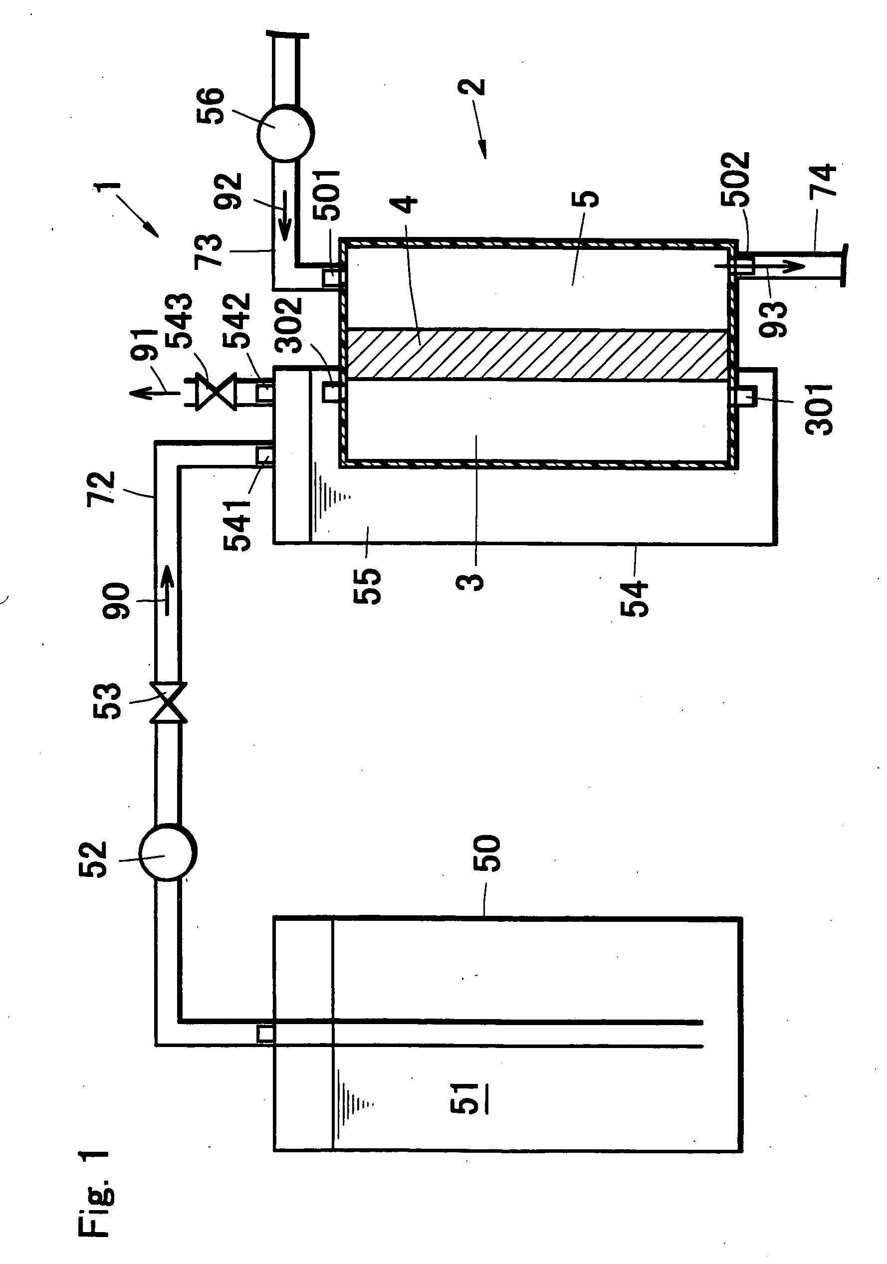
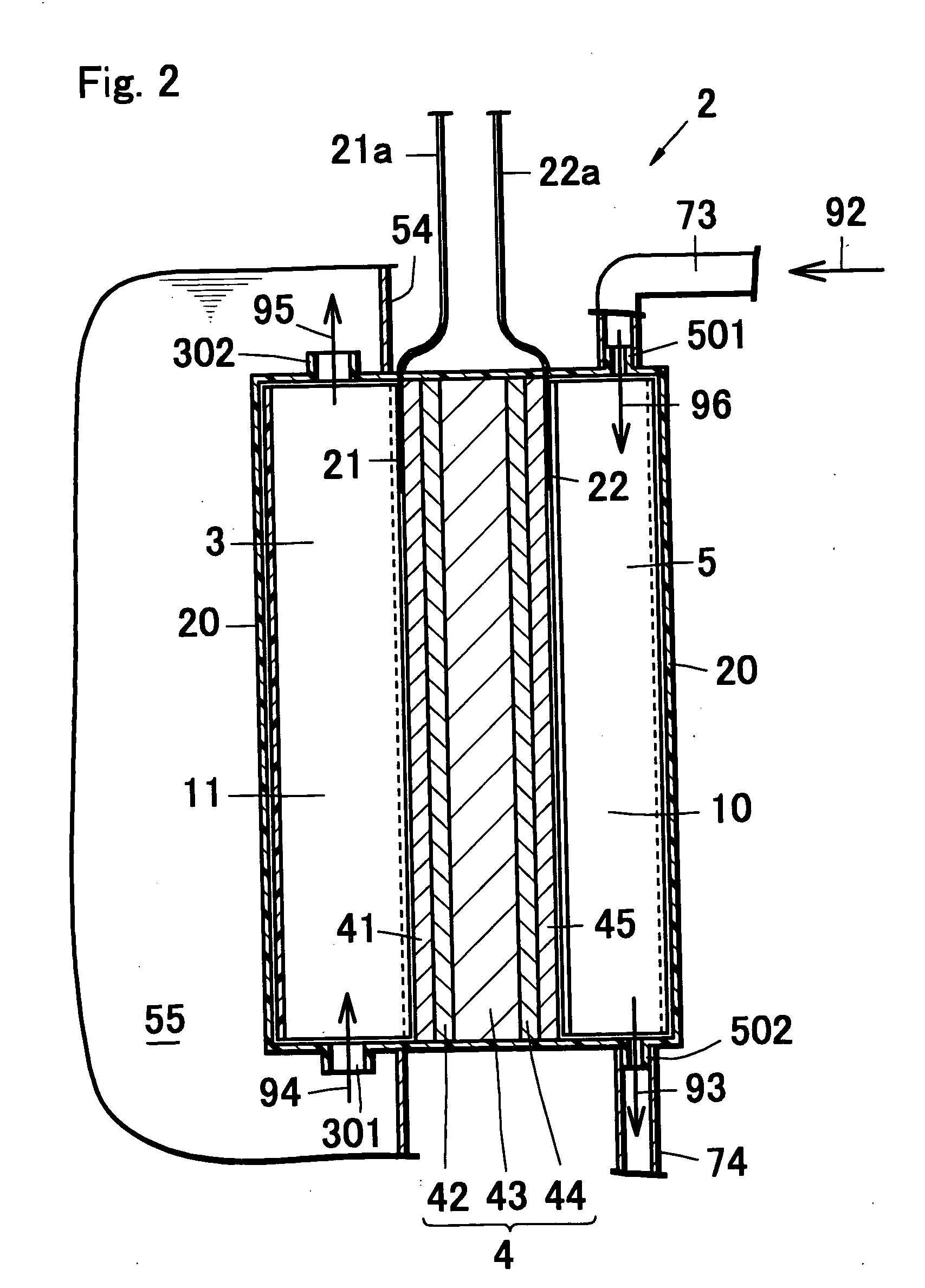
[0137]FIG. 1 is a schematic structural view showing a fuel cell system in the first embodiment of the present invention. FIG. 2 is a schematic structural view showing a fuel cell body for use in the fuel cell system of FIG. 1.

[0138] As shown in FIG. 1 and FIG. 2, a fuel cell system 1 has a fuel cell body 2 that is a power generation portion for generating electric power by electrochemically converting chemical energy of fuel to electric energy, and an auxiliary equipment system for operation such as feeding fuel or the like necessary for the power generation to the fuel cell body 2. Moreover, the fuel cell system 1 is a Direct Methanol Fuel Cell (DMFC) for generating electric power with use of a methanol solution exemplifying organic liquid fuel as fuel by directly extracting protons from the methanol.

[0139] As shown in FIG. 1, the fuel cell body 2 has an anode (fuel pole) 3, a cathode (air pole) 5 and a membrane electrode assembly 4. The membrane electrod...

second embodiment

[0163] (Second Embodiment)

[0164] Description is now given of a fuel cell system according to the second embodiment of the present invention. FIG. 7 is a schematic structural view showing the fuel cell system in the second embodiment of the present invention. A fuel cell system la in the present embodiment is almost identical in structure to the fuel cell system 1 in the first embodiment, and therefore description herein will be focused on difference therebetween.

[0165] The fuel cell system 1a in the second embodiment is a fuel cell system with use of a Direct Methanol Fuel Cell (DMFC) which generates electric power by directly extracting protons from methanol. The fuel cell body 2 shares the structure of the fuel cell system 1 in the first embodiment.

[0166] As shown in FIG. 7, the entire fuel cell body 12 is disposed so as to be completely immersed in an intermediate tank 54 that is auxiliary equipment for fuel feed.

[0167] Herein, FIGS. 8, 9A and 9B show the detailed structure of...

third embodiment

[0185] (Third Embodiment)

[0186] Description is now given of a fuel cell system according to the third embodiment of the present invention. FIG. 14 is a schematic block diagram showing the fuel cell system in the third embodiment of the present invention. A fuel cell system 1b in the third embodiment is almost identical in structure to the fuel cell system 1 in the first embodiment, and therefore description herein will be focused on difference therebetween.

[0187] The fuel cell system 1b in the third embodiment is a fuel cell system with use of a Direct Methanol Fuel Cell (DMFC) which generates electric power by directly extracting protons from methanol. A fuel cell body 212 shares the structure of the fuel cell system 1 in the first embodiment.

[0188] As shown in FIG. 14, the entire fuel cell body 212 is disposed inside an intermediate tank 254 that is auxiliary equipment for fuel feed in the state of being completely immersed in liquid fuel 55 contained in the intermediate tank 25...


PUM

PropertyMeasurementUnit
poweraaaaaaaaaa
poweraaaaaaaaaa
thicknessaaaaaaaaaa

Abstract

A fuel cell body has an anode having an anode-side separator with projections and depressions formed on its surface, a cathode, and a membrane electrode assembly disposed between the anode and the cathode, and the fuel cell body is disposed in a container for storing liquid fuel so that at least the anode side is immersed therein. Fuel passageways through which the liquid fuel flows are formed by regions surrounded by the projections and depressions on the surface of the separator and the membrane electrode assembly. By this, the downsized, simplified and lower power consuming structure of auxiliary equipment such as fuel feed system is achieved.

Description

BACKGROUND OF THE INVENTION [0001] The present invention relates to a fuel cell, and more particularly to a type of fuel cell that generates electric power by feeding organic liquid fuel such as methanol directly to an anode. [0002] Portable electronic equipment such as cell phones, personal digital assistants, notebook-sized personal computers, portable audios and portable visuals has been becoming popular. Such portable electronic equipment is conventionally driven by primary batteries or secondary batteries. Particularly, Nickel-Cadmium batteries or lithium-ion batteries are used as the secondary batteries, and development of downsized batteries with high-energy density have been developed. However, since the secondary batteries need to be charged for a specified period of time after consumption of a specific amount of electric power, the batteries supporting continuous long-run driving with short charging time have been demanded. [0003] In order to meet the demand, fuel cells op...

Claims


Application Information

Patent Timeline
Patent Type & Authority Applications(United States)
IPC IPC(8): H01M8/02H01M8/04H01M8/10H01M8/24
CPCH01M4/0407Y02B90/18H01M8/0247H01M8/0254H01M8/0258H01M8/0263H01M8/04156H01M8/04194H01M8/04298H01M8/04619H01M8/04753H01M8/04761H01M8/04776H01M8/04791H01M8/04955H01M8/1009H01M8/1011H01M8/247H01M8/2475H01M2250/30Y02E60/521H01M8/0221H01M8/241H01M8/2484Y02B90/10Y02E60/10Y02E60/50H01M8/2457
Inventor HASEGAWA, KENJIAOYAMA, TOSHIYUKIHIGASHIONJI, MASARUSHIMOTASHIRO, MASAFUMIONO, MASAYUKIHORI, KENYAODAGIRI, MASARU
Owner PANASONIC CORP
Why Eureka
Try Eureka