Method and apparatus for ionization film formation
a technology of ionization film and ionization film, which is applied in the field of ionization film formation and ionization film formation apparatus, can solve the problems of adversely affecting the quality of the film formation, and achieve the effects of improving the ionization efficiency of vaporized particles, preventing the sputtering of hot-cathode filaments, and significantly improving the life of hot-cathode filaments
- Summary
- Abstract
- Description
- Claims
- Application Information
AI Technical Summary
Benefits of technology
Problems solved by technology
Method used
Image

Examples
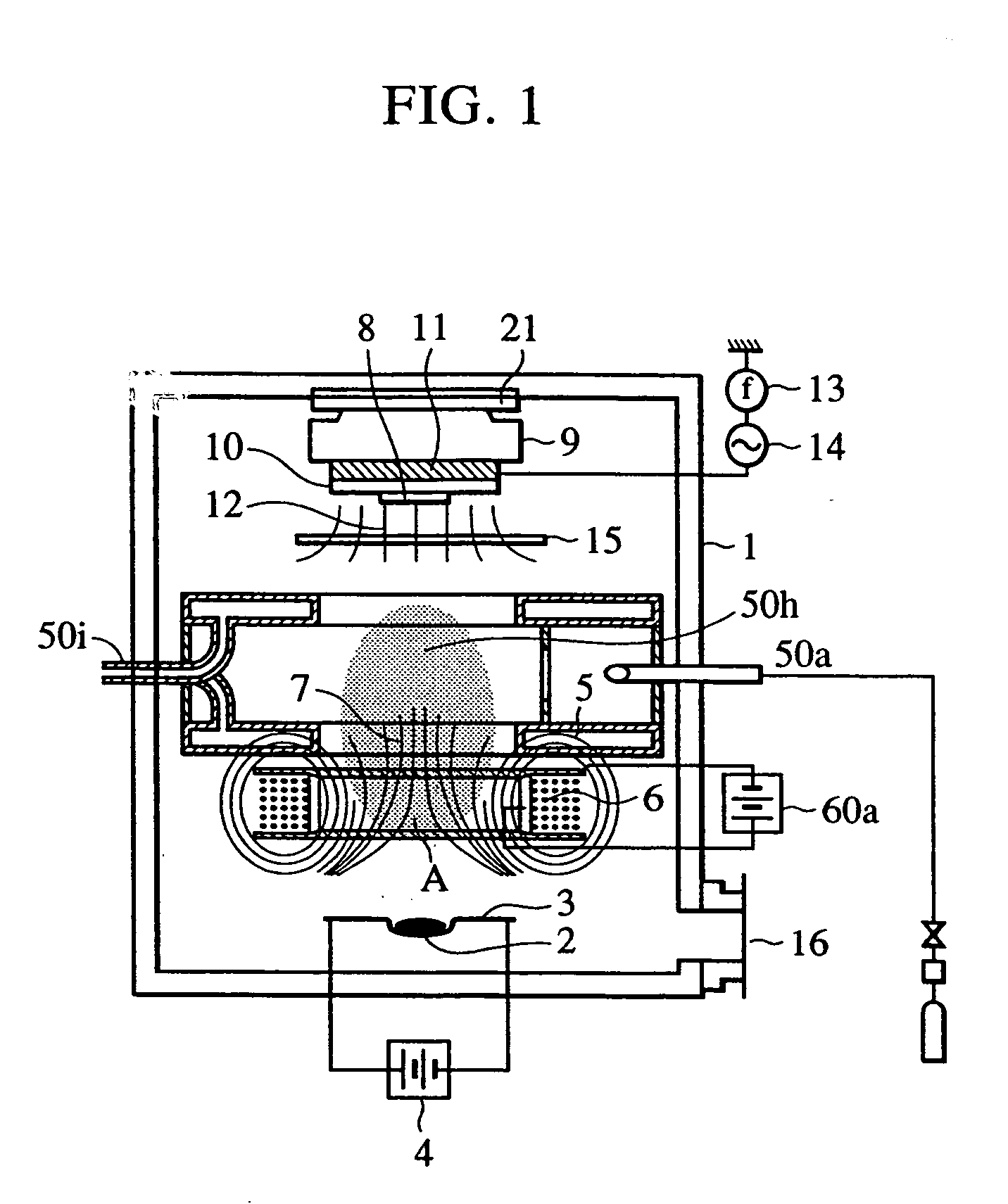
first embodiment
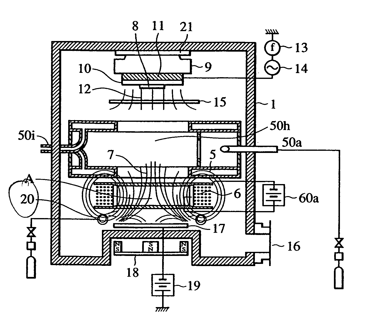
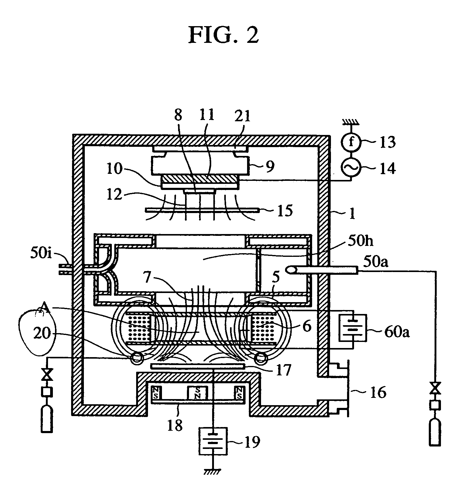
Regarding the configuration of the ionization sputtering apparatus according to the present embodiment, points of difference from the configuration of the apparatus for ionization film formation in the first embodiment will be described bellow with reference to the drawings.
The exhaust system 16 is a combined exhaust system capable of evacuating the chamber 1 from atmospheric pressure to a pressure on the order of 1×10⁻⁵ Pa. The exhaust velocity is adjusted with a conductance valve which is an exhaust velocity adjustor not shown in the drawing, and, thereby, the residence time of the gas for discharge in the chamber can be controlled.
The target 17 is in the shape of a disk on the order of, for example, 3 mm in thickness and 3 inches (76.2 mm) in diameter, and is arranged on the sputtering chamber 1 with a backing plate and an insulation material therebetween. A magnet mechanism 18 is arranged at the rear of the target 17, and, therefore, magnetron sputtering can be performed. The...
example 1
In a manner similar to that in the aforementioned first embodiment, ionization film formation was performed continuously, and the life of the filament 50b was measured. The materials and conditions were as follows: vaporization material: Fe distance between crucible and substrate: 155 mm substrate dimension: diameter 2 inches (50.8 mm) substrate material: glass pressure in sputtering chamber: 0.5 Pa ionization gas: He magnetic flux density at point A: 200 G ionization mechanism grid voltage: 50 V ionization mechanism grid current: 20 A ionization mechanism floating power supply voltage: −40V lead-in electrode voltage: minimum value 0 V, maximum value −60 V lead-in electrode voltage frequency: 500 kHz lead-in electrode voltage duty: 1 to 100
The results are shown in Table 1.
example 2
A sample substrate having a bottom width of 0.25 μm and an aspect ratio of 4 was subjected to ionization film formation under the same conditions as that in Example 1, and, therefore, a sample was prepared.
PUM
| Property | Measurement | Unit |
|---|---|---|
| volume | aaaaa | aaaaa |
| pressure | aaaaa | aaaaa |
| width | aaaaa | aaaaa |
Abstract
Description
Claims
Application Information