Multilayer coated corrosion resistant article and method of production thereof

a technology of corrosion resistance and coating, applied in the direction of transportation and packaging, synthetic resin layered products, mechanical instruments, etc., can solve the problems of increasing production costs, increasing production costs, and increasing production costs, so as to improve the heat resistance, broaden the range of processes, and enhance the effect of chromated or phosphated surfaces

Inactive Publication Date: 2005-02-10
ELISHA HLDG LLC
View PDF10 Cites 51 Cited by
  • Summary
  • Abstract
  • Description
  • Claims
  • Application Information

AI Technical Summary

Benefits of technology

[0019] The inventive process is also a marked improvement over conventional methods by reducing, if not eliminating, chromate and / or phosphate containing compounds (and issues attendant with using these compounds such as waste disposal, worker exposure, among other undesirable environmental impacts). While the inventive process can be employed to enhance chromated or phosphated surfaces, the inventive process can replace these surfaces with a more environmentally desirable surface. The inventive process, therefore, can be “substantially chromate free” and “substantially phosphate free” and in turn produce articles that are also substantially chromate (hexavalent and trivalent) free and substantially phosphate free. The inventive process can also be substantially free of heavy metals such as chromium, lead, cadmium, cobalt, barium, among others. By substantially chromate free, substantially phosphate free and substantially heavy metal free it is meant that less than 5 wt. % and normally about 0 wt. % chromates, phosphates and / or heavy metals are present in a process for producing an article or the resultant article. In addition to obviating chromate containing processes, the inventive method forms a layer having greater heat resistance, flexibility, among other properties, than conventional chromate coatings. The improved heat resistance broadens the range of processes that can be performed subsequent to forming the inventive layer, e.g., heat cured topcoatings, bending, deforming, stamping / shaping, riveting, among other processes.

Problems solved by technology

Such pipes are located under the body of the vehicle and are exposed to severe outdoor environments including road water and rock salt.
The pipes are also prone to damage or wear by stones or mud spattered by the rotating tires of the vehicle.
Conventional metal pipes without protective coating do not meet such requirements.
In addition, the automotive industry has enormous quantity demands, as in the case of brake pipes and fuel pipes.

Method used


Image

  • Multilayer coated corrosion resistant article and method of production thereof
  • Multilayer coated corrosion resistant article and method of production thereof
  • Multilayer coated corrosion resistant article and method of production thereof

Examples


example 1

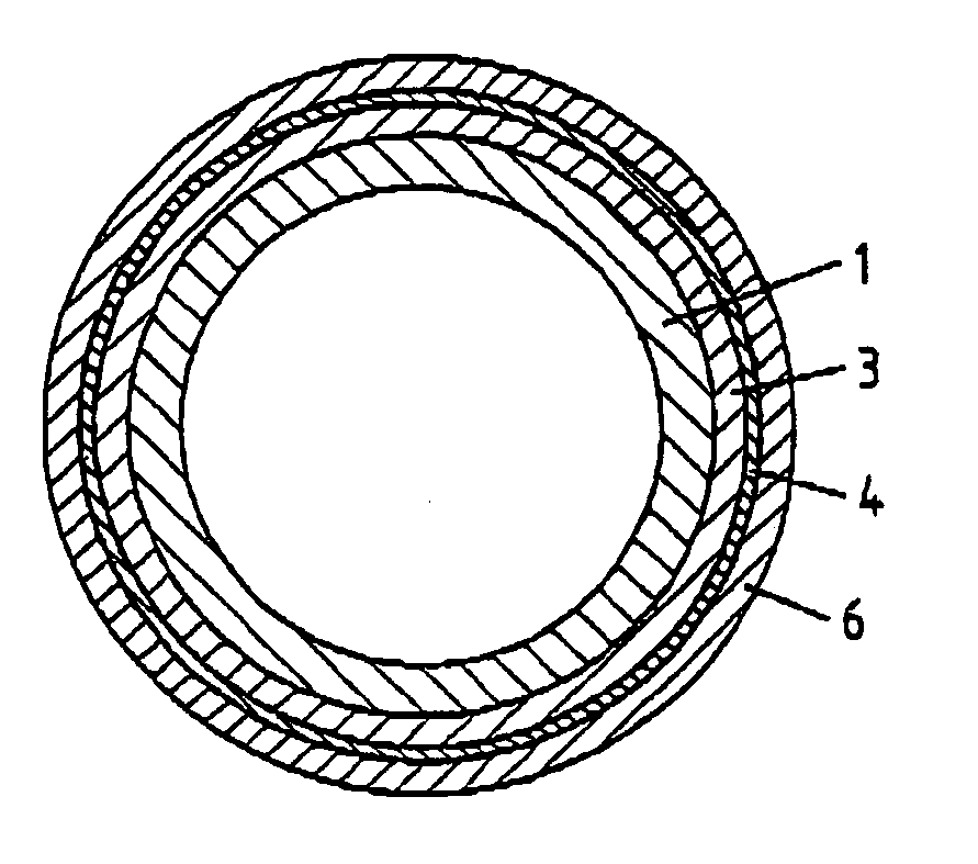
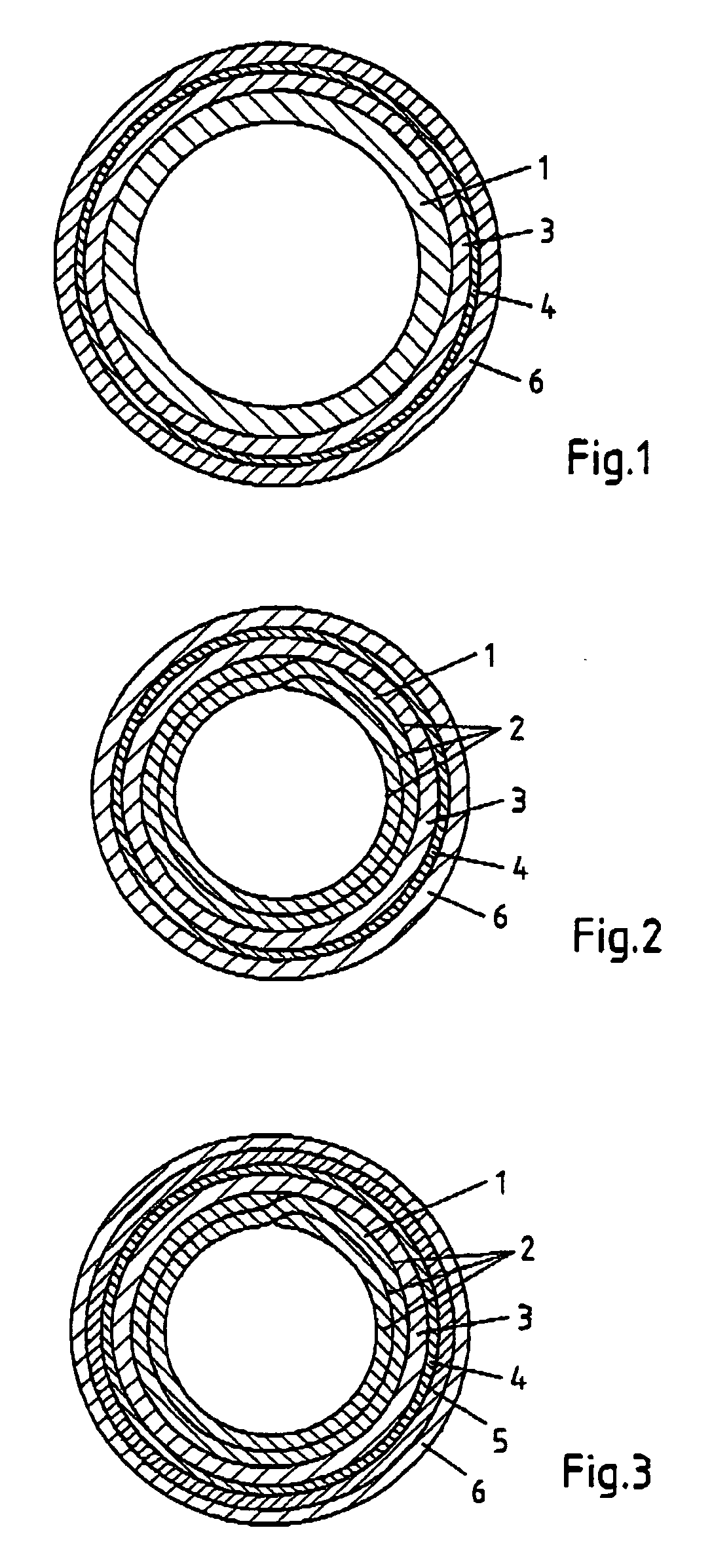
[0147] PVF coated single-wound steel tubes of the type as depicted in FIG. 1 were prepared on a continuous process line in accordance with the following procedure: [0148] (1) Metal tube: Single-wound steel tube 1 having 8 mm outer diameter and 0.7 mm wall thickness fabricated from an SPCC steel sheet. [0149] (2) Zinc plating layer: A zinc plating layer 3 of 25 microns thickness was cathodically formed on the outer circumferencial surface of the single-wound steel tube 1 by employing an acidic electrolyte (pH 2.8) containing 790 g / l ZnSO4, 6 g / l boric acid, 4 g / l ZnCl2 and 16 m / l organic additives and applying an electric current at a density of 120 A / dm2 at a temperature of 55-60° C.

[0150] Zinc electroplating was carried out in a continuous plating bath 10 as depicted in FIGS. 4 and 5. Referring now to FIG. 4, the plating bath 10 comprises an inner chamber 11 (“electrolyte bath”) and two outer chambers 12,13 (“spill chambers”). Electroplating takes place in the inner electrolyte ba...

example 2

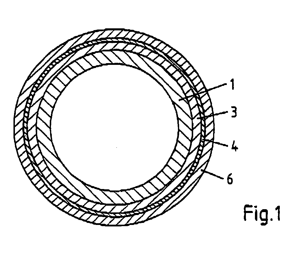
[0162] PVF coated double-wound steel tubes of the type as depicted in FIG. 2 were prepared on a continuous process line in accordance with the following procedure: [0163] (1) Metal tube: Double-wound steel tube 1 having 4.75 mm outer diameter and 0.7 mm wall thickness was fabricated from an SPCC steel sheet having a copper layer 2 of 5 μm film thickness. [0164] (2) A zinc plating layer 3 of approximately 25 μm thickness was formed in the same manner as in step (2) of Example 1. [0165] (3) A silicate film 4 of approximately 200-300 Å thickness was formed in the same manner as in step (3) of Example 1. [0166] (4) A polyvinyl fluoride layer 6 of approximately 20 μm thickness was formed in the same manner as in step (4) of Example 1. [0167] (5) Testing: Corrosion resistance testing (salt spray test according to ASTM B 117) and adhesion testing (cross cut test according to ISO 2409) were conducted in the same manner as described in Example 1. The test results are summarized in Table 1. A...

example 3

[0168] Example 2 was repeated varying the dwell time in step (3) in the formation of the silicate film 4. The resulting coated tubes are of the type as depicted in FIG. 2.

[0169] Conditions for silicate film formation

ExampleNa2SiO3 concpHCurrentTemp.TimeEXAMPLE 3A10%10.5  2 A / dm275 20 secEXAMPLE 3B10%10.5  2 A / dm275 30 secEXAMPLE 3C10%10.5  2 A / dm275 60 secEXAMPLE 3D10%10.5  2 A / dm275 90 secEXAMPLE 3E10%10.5  2 A / dm275120 secEXAMPLE 3F10%10.5  2 A / dm223 30 secEXAMPLE 3G10%10.5  2 A / dm223120 secEXAMPLE 3H 5%10.5  3 A / dm275 30 secEXAMPLE 3I 5%10.5  3 A / dm275120 secEXAMPLE 3J15%10.51.5 A / dm275 30 secEXAMPLE 3K15%10.51.5 A / dm275120 sec

[0170] Testing: Corrosion resistance testing (salt spray test according to ASTM B 117) and adhesion testing (cross cut test according to ISO 2409) were conducted in the same manner as described in Example 1. The test results are summarized in Table 1.

[0171] The results show that the dwell time in the electrolyte bath during silicate film formation and, ...


PUM

PropertyMeasurementUnit
thicknessaaaaaaaaaa
thicknessaaaaaaaaaa
thicknessaaaaaaaaaa

Abstract

The disclosure relates to a corrosion resistant article comprising a metal body 1 and a protective coating applied on at least one surface of said metal body 1, said protective coating comprising: (a) a zinc layer 3 comprising metallic zinc; (b) a silicate layer 4 comprising at least one silicate; and (c) a synthetic resin layer 6 comprising at least one fluoroplastic material such as, for example, polyvinylfluoride. In particular, the disclosure relates to a corrosion resistant brake pipe or fuel pipe having a protective coating for use in motor vehicles. The protective coating is substantially free of chromates and phosphates and, hence, environmentally acceptable.

Description

FIELD OF THE INVENTION [0001] The instant invention relates to multilayer coated corrosion resistant articles and a method of production thereof. In particular, the instant invention relates to multilayer coated corrosion resistant metal fluid carrying systems which can be used, for example, as heating ventilation and cooling (HVAC), brake pipes or fuel pipes in automobiles or as feed channels for feeding oil or air to various kinds of machines and equipments. BACKGROUND OF THE INVENTION [0002] Safety sensitive automobile components such as brake pipes and fuel pipes for motor vehicles must meet strict requirements with regard to corrosion and wear resistance. Such pipes are located under the body of the vehicle and are exposed to severe outdoor environments including road water and rock salt. The pipes are also prone to damage or wear by stones or mud spattered by the rotating tires of the vehicle. As they are used in such harsh outdoor environments, such pipes are required to have...

Claims


Application Information

Patent Timeline
Patent Type & Authority Applications(United States)
IPC IPC(8): B32B1/08B32B15/08F16L58/10
CPCB32B1/08B32B15/08F16L58/10Y10T428/12792Y10T428/12799Y10T428/12618Y10T428/12569B32B27/304B32B2311/12B32B2311/20B32B2311/22B32B2311/24B32B2311/30B32B2327/18
Inventor KLOS, KLAUS-PETERGROLMES, HOLGER MANFRED
Owner ELISHA HLDG LLC
Why Eureka
Try Eureka