Dual beam system

a dual beam system and beam technology, applied in the field of charged particle beam systems, can solve the problems of secondary particles, interference with various other functions of the dual beam system, and alter the trajectory and achieve the effect of removing the blurring of the ion beam

Active Publication Date: 2005-02-17
FEI CO
View PDF7 Cites 46 Cited by
  • Summary
  • Abstract
  • Description
  • Claims
  • Application Information

AI Technical Summary

Benefits of technology

[0015] Some embodiments include a secondary particle detector that is positioned such that the magnetic field of the SEM lens helps in the collection of secondary particles. Another embodiment uses monoisotopic gallium that eliminates blurring of the ion beam caused by the different effects of the SEM magnetic field with the different isotopes of gallium.

Problems solved by technology

One difficulty with such systems is that the final lens of the scanning electron microscope produces a magnetic field, which alters the trajectory of the ion beam and also interferes with various other functions of the dual beam system.
The magnetic field of the SEM, however, changes the path of the secondary particles and makes them difficult to collect.
When a work piece in a charged particle beam system is composed of an insulating material, such as quartz, the work piece tends to accumulate electrical charge that adversely affects the primary beams and secondary particles.
An electron flood gun differs from an electron microscope in that the flood gun lack precise optics options and produces a relatively broad beam of low energy electrons.
The magnetic field of the SEM changes the path of the neutralizing electrons from the flood gun and makes it difficult to direct them accurately toward the work piece.
Turning the SEM lens on and off creates its own set of problems.
Systems are now being used as production equipment and such delays are unacceptable.
Such lenses have low inductance, but changing the lens current changes the power dissipation of the lens, which can upset the thermal equilibrium of the system, thereby reducing resolution.
If one designed a dual beam system to compensate for the effects of a constant magnetic field from the SEM objective lens, the problem would not be solved completely, because the magnetic field is not constant.
A system in which the SEM is tilted cannot easily use retarding field options, since the tilt eliminates the symmetry of the retarding electric field and causes undesirable aberrations in the primary electron beam and difficulty in the collection of secondary electrons.

Method used


Image

  • Dual beam system
  • Dual beam system
  • Dual beam system

Examples


Embodiment Construction

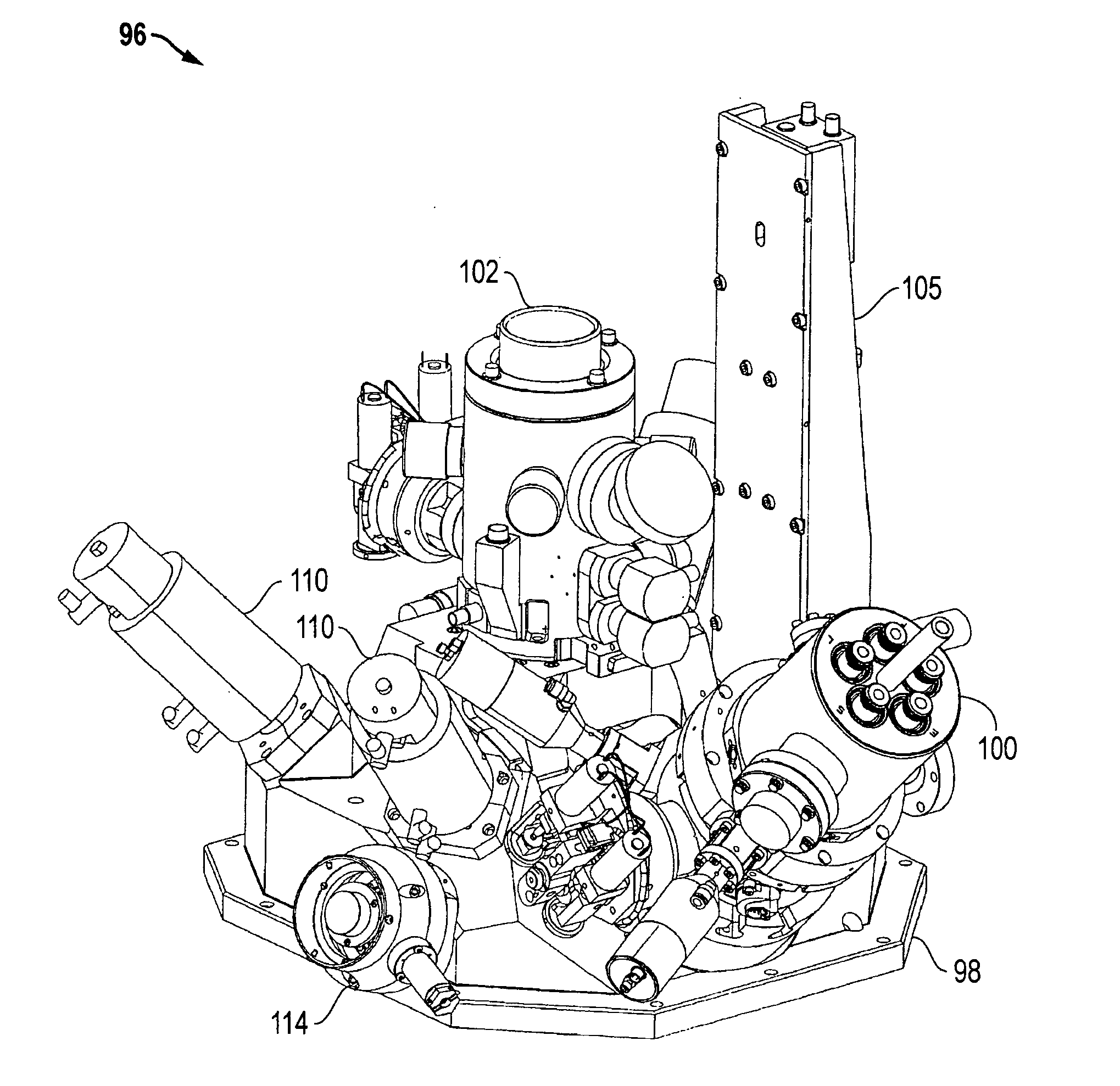
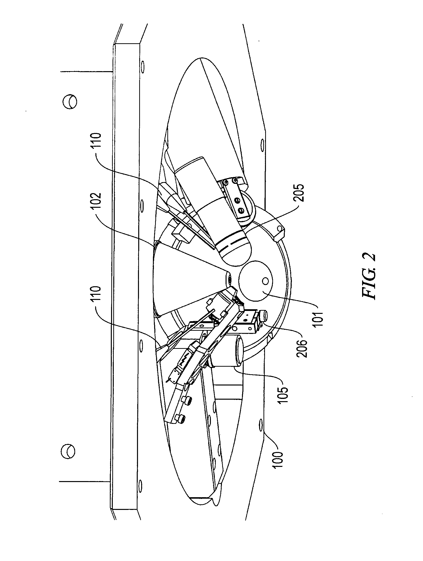
[0034]FIG. 1 shows a portion of a dual beam system 96 that includes a turret 98 upon which are mounted an scanning electron microscope 100, an ion beam column 102, a light microscope 105, one or more gas injection systems (GIS) 110, and an electron detector 114 that detects electrons collected through the lens of SEM 100 and deflected away from the primary electron beam axis. FIG. 2 shows the same component as seen from underneath, that is, as seen from the work piece surface. A charge neutralization flood gun 204 and a secondary particle detector 205, such as a channel detector electron multiplier (CDEM) that detects particles generated from the work piece by the impact of ions from ion beam column 102, are visible in FIG. 2.

[0035] Although the ion beam and the electron beam ideally point to the identical spot on the work piece, the physical sizes of the electron beam column and the ion beam column typically prevent them from being positioned very close to the surface and directed...


PUM


Abstract

A dual beam system includes an ion beam system and a scanning electron microscope with a magnetic objective lens. The ion beam system is adapted to operate optimally in the presence of the magnetic field from the SEM objective lens, so that the objective lens is not turned off during operation of the ion beam. An optional secondary particle detector and an optional charge neutralization flood gun are adapted to operate in the presence of the magnetic field. The magnetic objective lens is designed to have a constant heat signature, regardless of the strength of magnetic field being produced, so that the system does not need time to stabilize when the magnetic field is changed.

Description

[0001] This application claims priority for U.S. Provisional Patent Application No. 60 / 487,792, filed Jul. 14, 2003, which is hereby incorporated by reference.TECHNICAL FIELD OF THE INVENTION [0002] The present invention relates to charged particle beam systems, and in particular to systems including an ion beam column and an electron beam column using a magnetic objective lens. BACKGROUND OF THE INVENTION [0003] Charged particle beam systems are used in a variety of applications, including the manufacturing, repair, and inspection of miniature devices, such as integrated circuits, magnetic recording heads, and photolithography masks. Dual beam systems often include a scanning electron microscope (SEM) that can provide a high-resolution image with minimal damage to the target, and an ion beam system, such as a focused or shaped beam system, that can be used to alter substrates and to form images. [0004] One common application for a dual beam system is to expose a buried portion of a...

Claims


Application Information

Patent Timeline
Patent Type & Authority Applications(United States)
IPC IPC(8): H01J37/02H01J37/141H01J37/08H01J37/26H01J37/28H01J37/30
CPCH01J37/026H01J37/08H01J37/141H01J2237/0042H01J2237/31749H01J2237/1405H01J2237/28H01J2237/317H01J2237/0805
Inventor HILL, RAYMONDSANFORD, COLIN AUGUSTSCIPIONI, LAWRENCEDIMANNA, MARKTANGUAY, MICHAEL
Owner FEI CO
Why Eureka
Try Eureka