
Organic photoreceptor and image forming method

a photoreceptor and organic technology, applied in the field of organic photoreceptors, can solve the problems of insufficiently minimizing the generation of black spots, difficult to achieve sufficient image density, and affecting the image quality of the image, and achieve excellent potential stability

Inactive Publication Date: 2005-02-17
KONICA CORP
View PDF6 Cites 7 Cited by
  • Summary
  • Abstract
  • Description
  • Claims
  • Application Information

AI Technical Summary

Benefits of technology

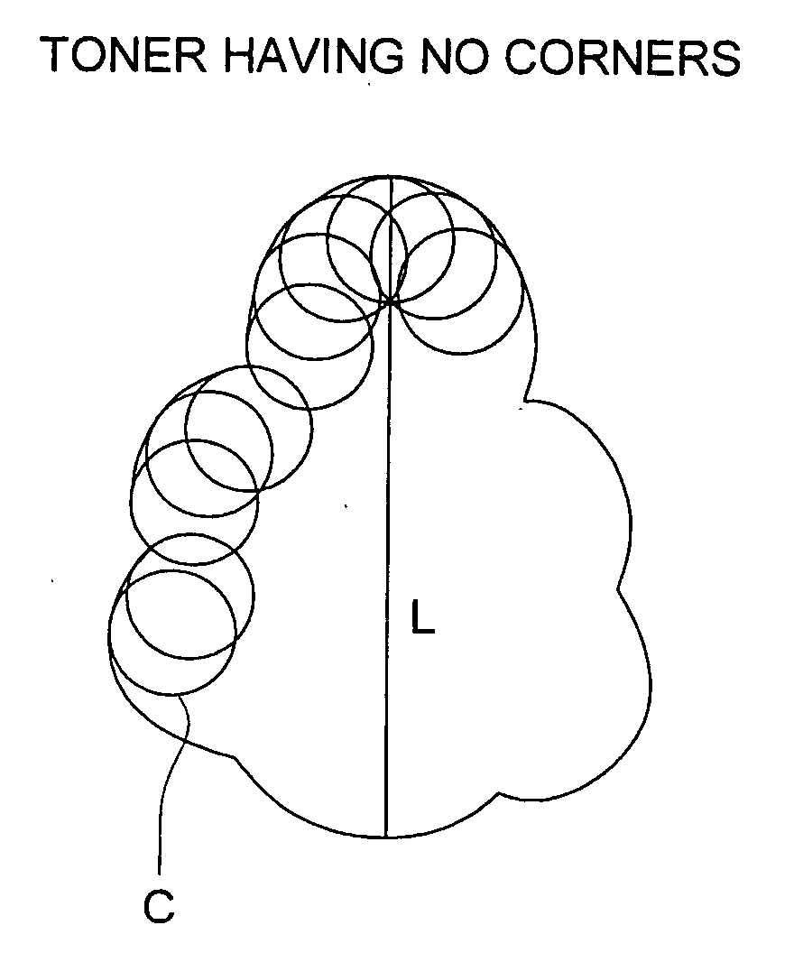
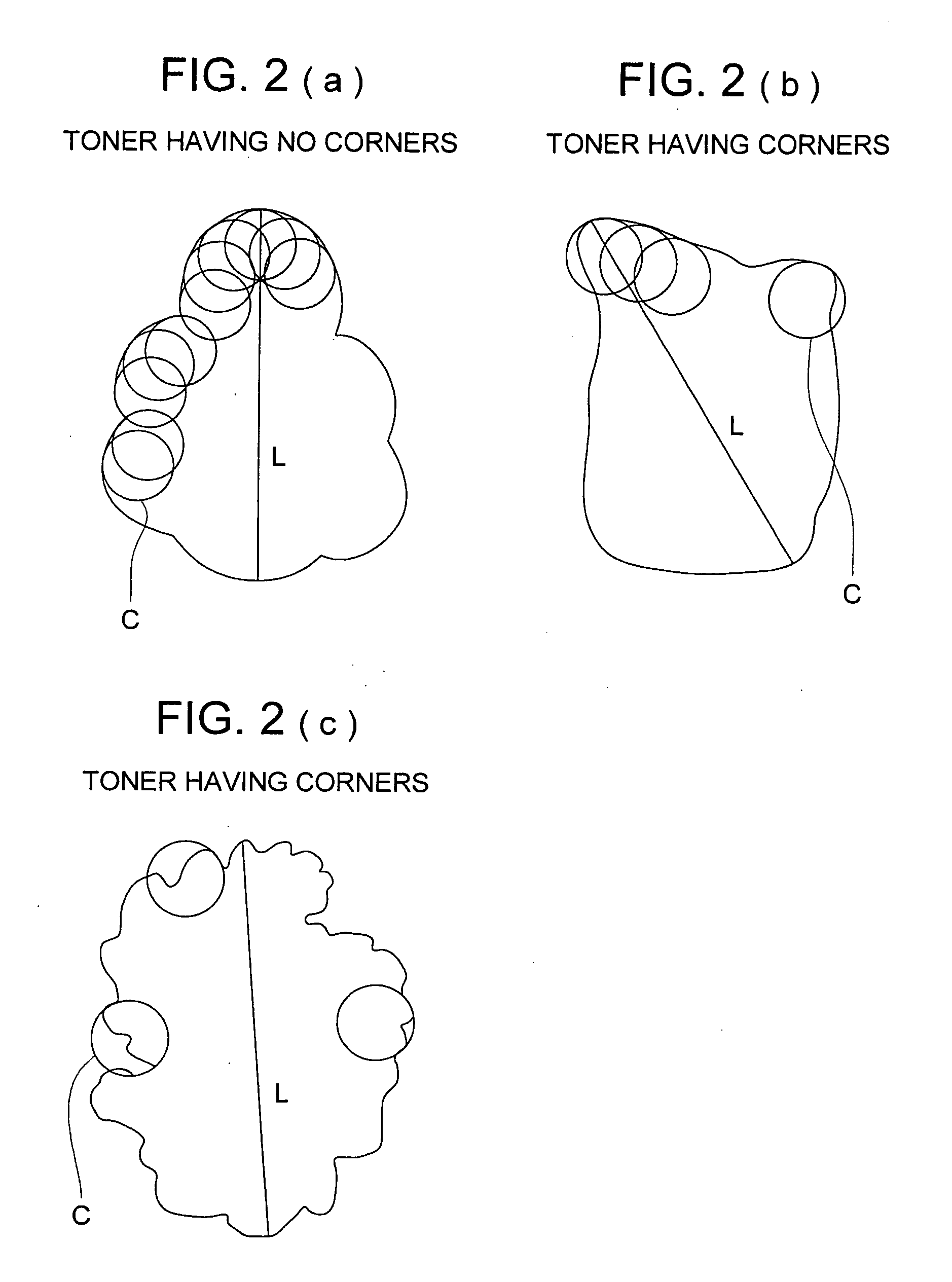
When the toner satisfying at least one of the above mentioned conditions (1) through (5) is employed in combination with a photoreceptor having surface characteristics according to the invention, generation of image deficiency such as white spots or black spots in the reverse development are inhibited, cleaning characteristics are improved, and therefore, good image is obtained. The conditions (2) and (5) are more important for displaying the advantages of the invention in comparison with the other conditions (1), (3) and (4). However, such conditions as (1), (3) and (4) are the characteristics to display the advantage of the invention. Particularly the combination of the toner satisfying all of the conditions (1) through (5) and the photoreceptor having specific surface layer, that is, a photoreceptor having charge transport layer containing CTM of a steric isomer mixture as the surface layer improves markedly the incompatible image deficiencies of white spots and black spots.

Problems solved by technology

As a result, problems in terms of images tend to surface, which do not occur at room temperatures.
However, at an ambience of high temperature and high humidity, generation of black spots is not sufficiently minimized.
As a result, problems occur in which it is difficult to achieved sufficient image density.
In the image forming apparatus utilizing such a photoreceptor, image problems occur such as black spots on white backgrounds and white undeveloped spots on black backgrounds or halftones, which are not compatible with each other.
The polymerization toner has spherical shape and it has greater adhesive force to a photoreceptor, and therefore, induces a problems such as reducing transferring characteristics to a image forming sheet from the photoreceptor or cleaning characteristics, whereby the sufficient image density is not expected and sometimes generates an image deficiency such as white spot mentioned above.

Method used


Image

  • Organic photoreceptor and image forming method
  • Organic photoreceptor and image forming method
  • Organic photoreceptor and image forming method

Examples


example 1

Synthesis Example 1 (Synthesis Example of Exemplified Compound T83)

Dissolved in 40 ml of dimethylformamide were 10 g of the compound represented by the aforesaid formula, and the resulting solution was heated to 40° C. Subsequently, 9.2 g of phosphorous oxychloride were gradually added dropwise (the temperature of the resulting mixture increased to the range between 40 and 70° C. due to heat generation). The reaction composition was stirred for 3 hours while maintaining the temperature at about 70° C. After cooled to 40° C., any excessive phosphorous oxychloride sufficiently underwent hydrolysis and deposited crystals were separated by filtration. The resultant crystals were washed while suspended in water and washing was repeated until the washing water became neutral, whereby 9.25 g (85 percent) bisformyl compound, represented by the structural formula described below, were prepared.

Dissolved in 50 ml of tetrahydrofuran were 4 g of bisformyl compound prepared as above and 9.3...

example 2

Synthesis Example 2 (Synthesis Example of Exemplified Compound T74)

Charged into a four-necked flask fitted with a cooling pipe and a thermometer under a flow of N2 gas were 20 g of the aforesaid 4-methoxytriphenylamine, 32 g of dimethylformamide, and 80 ml of toluene, and the resulting mixture was mixed. While keeping at 60 to 70° C., 76.02 g of phosphorus trichloride were gradually dripped. Thereafter, the resulting mixture underwent reaction at approximately 70° C. for 20 hours. After the reaction, the inner temperature was decreased to approximately 50° C., and subsequently, 500 ml of water at 60 to 70° C. was gradually dripped (attention was paid so that the inner temperature did not exceed 70° C.). After stirring for one hour, 400 ml of toluene were added and washing was carried out until the resulting washing water became neutral in pH. After concentration, recrystallization was performed employing isopropyl alcohol, whereby 16.46 g (64 percent) of 4,4′-diformyl-4″-methoxyph...

example 3

Synthesis Example 3 (Synthesis Example of Exemplified Compound T20)

Dissolved in 32 g of phosphorus oxychloride were 10 g of the compound represent by the formula described above, and the resulting solution was heated to 50° C. Subsequently, 22 ml of dimethylformamide were gradually dripped (the temperature of the resulting mixture increased between 40 and 70° C. due to heat generation). The reaction composition was stirred for 15 hours while controlling the temperature at approximately 90° C. After the temperature was allowed to lower itself to 40° C., the residual phosphorus oxychloride was completely hydrolyzed, and deposited crystals were collected through filtration and then suspended in water. The collected crystals were washed with water while suspended and washing was repeated until the resulting washing water became neutral in pH, whereby 9.25 g (77 percent) of the bisformyl compound represented by the structural formula described below was obtained.

Dissolved in 20 ml o...


PUM


Abstract

An electrophotographic photoreceptor is disclosed. The charge transport material comprising a mixture of stereoisomers as a charge transport material and glass transition point Tgb of the binder resin of the charge transport layer and glass transition point Tgl of the charge transport layer satisfy100° C.<Tgl<Tgb(both Tgb and Tgl in ° C.).An image forming method employing the photoreceptor is also disclosed.

Description

FIELD OF THE INVENTION The present invention relates to an organic photoreceptor employed in the field of copiers and printers, and an image forming method, an image forming apparatus, and a processing cartridge using the same. BACKGROUND OF THE INVENTION With regard to electrophotographic photoreceptors, organic photoreceptors, which exhibit advantages in environmental protection as well as ease of production, have been mainly employed instead of inorganic photoreceptors. Currently, organic photoreceptors, utilizing various materials, have been developed. In recent years, separate function type photoreceptors have played the main roll in which charge generation and charge transport function employ different materials. Of these, laminated-layer type organic photoreceptors (hereinafter occasionally referred to simply as photoreceptors) are widely employed in which a charge generating layer and a charge transport layer are laminated to each other. Further, when attention is paid t...

Claims


Application Information

Patent Timeline
Patent Type & Authority Applications(United States)
IPC IPC(8): G03G5/05G03G5/06G03G9/08
CPCG03G5/0517G03G5/0521G03G5/0592G03G5/0596G03G9/0827G03G5/0614G03G5/0666G03G5/0672G03G9/0819G03G5/06G03G5/06144G03G5/061443G03G5/061473
Inventor SHIBATA, TOYOKOABE, NAOTOITAMI, AKIHIKOOSHIBA, TAKEO
Owner KONICA CORP
Learn More