Method of treating sputtering target to reduce burn-in time and sputtering target thereof and apparatus thereof

a sputtering target and target technology, applied in the field of dry treating a sputtering target, can solve the problems of inherently problematic characteristics, uniformity and burn-in time requirements of sputtering targets, nickel, chromium, cobalt, etc., and achieve the effect of reducing the uniformity of wafers

Inactive Publication Date: 2005-02-24
PRAXAIR ST TECH INC
View PDF10 Cites 17 Cited by
  • Summary
  • Abstract
  • Description
  • Claims
  • Application Information

AI Technical Summary

Benefits of technology

[0013] The magnetron sputtering apparatus should treat the surface of the target assembly in an inert environment such as argon. The process conditions recited above will effectively treat the surface of the target assembly so that the Rs uniformity of a wafer can be reduced by at least 10% or a Rs uniformity percent of a wafer can be reduced to less than about 1.5%, preferably less than about 1.20% and most preferably less than about 1.10%.

Problems solved by technology

The typical manufacturing processes for sputter targets result in targets with surface defects.
Additionally, the materials comprising the sputter targets, such as titanium, aluminum, tantalum, nickel, chromium, cobalt, copper and alloys thereof, have inherently problematic characteristics (i.e., uniformity and burn-in time requirements) that are a result of the machining process.
These inherent defects and characteristics generally have an adverse effect on the end user of the sputter target product.
Among the undesirable effects of sputter target manufacture is the lengthy burn-in time for a new sputter target at the customer site.
Typically, sputter targets, such as titanium targets, exhibit poor film uniformity during the early stages of target use.
Deposition without this burn-in cycle would result in a relatively high reject rate of poor quality wafers.
Thus, a burn-in cycle is generally required to achieve a sputter surface that will provide the desired film uniformity, thus requiring a customer to waste valuable processing time and materials.
These methods of material removal are time consuming, labor intensive, costly, dirty and provide inconsistent results.
While polishing to a mirror finish may provide a good surface finish, it requires extensive preparation and time, usually 24 hours, which is unsuitable for a production environment, and there is no guarantee the same result may be obtained consistently for subsequent targets.
This non-value step impacts the entire manufacturing process and can contribute to increased cost of production.
To illustrate, sputtering systems are very expensive and downtime on this equipment is expensive.
Burn-in of a new target generally takes at least one hour that cannot be used for production.

Method used


Image

  • Method of treating sputtering target to reduce burn-in time and sputtering target thereof and apparatus thereof
  • Method of treating sputtering target to reduce burn-in time and sputtering target thereof and apparatus thereof

Examples


example

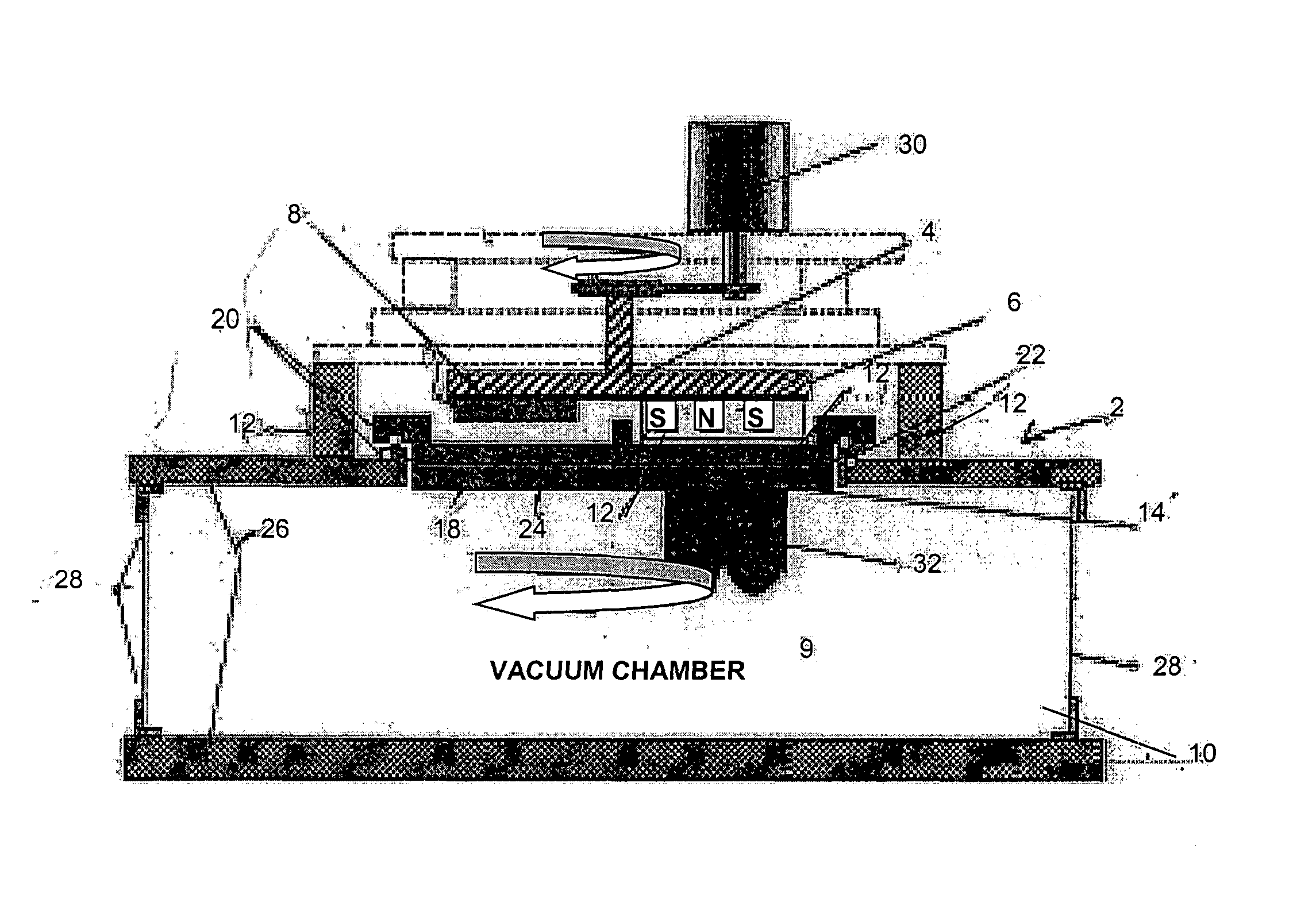
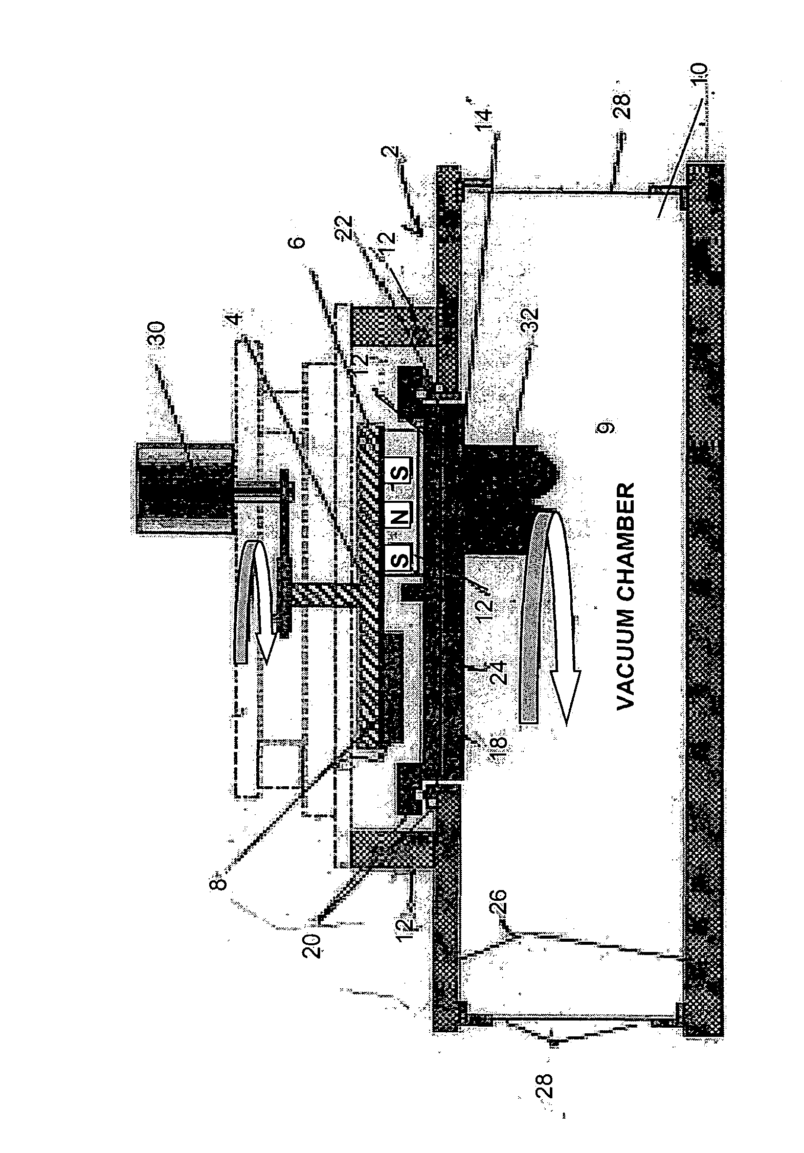
[0020] Using the magnetron sputtering apparatus as described in the drawing, the magnet assembled was energized with 0.3 kW power for 8 minutes at 2.5 micron argon. Rs uniformity of a wafer surface was determined for several wafers. After the Rs uniformity of a wafer surface was determined, the target surface was machined by 0.05 mm to simulate a new target surface. The target surface was then treated by the sputtering plasma at low power as shown below. The results are shown in the following table.

Wafer / Rs UniformitySampleTreatment(1 Sigma %)1as above1.20%11 kW at 8 minutes1.04%2as above1.46%21 kW at 8 minutes1.28%3as above1.54%4as above1.33%

“As above” means 0.3 kW, 8 minutes, 2.5 microns argon.

[0021] Normally, the process condition for normal burn-in is an incremental step process to a maximum power of at least 8 kw for at least 3 hours. Using the novel treatment of this invention, the burn-in time necessary to qualify the target for use in production is reduced. The novel trea...


PUM

PropertyMeasurementUnit
poweraaaaaaaaaa
poweraaaaaaaaaa
poweraaaaaaaaaa

Abstract

A method for dry treating a sputtering target using a sputtering ion plasma at low power to effectively reduce burn-in time of the target; the target so produced; and apparatus used for the target treatment.

Description

FIELD OF THE INVENTION [0001] This invention relates to a method of dry treating a sputtering target to achieve an enhanced finish on the surface that effectively reduces burn-in time of the target and the target and opposition for the treating thereof. BACKGROUND OF THE INVENTION [0002] In the manufacture of sputtering targets used for many applications, such as the semi-conductor industry, it is desirable to produce a target with a sputter surface that will provide film uniformity during sputtering onto a wafer such as a semi-conductor wafer. The typical manufacturing processes for sputter targets result in targets with surface defects. Additionally, the materials comprising the sputter targets, such as titanium, aluminum, tantalum, nickel, chromium, cobalt, copper and alloys thereof, have inherently problematic characteristics (i.e., uniformity and burn-in time requirements) that are a result of the machining process. These inherent defects and characteristics generally have an a...

Claims


Application Information

Patent Timeline
Patent Type & Authority Applications(United States)
IPC IPC(8): C23C14/32C23C14/34C25F1/00
CPCC23C14/3407C23C14/32C23C14/34C25F1/00
Inventor MCDONALD, PETER H.
Owner PRAXAIR ST TECH INC
Why Eureka
Try Eureka