

Processing apparatus
- Summary
- Abstract
- Description
- Claims
- Application Information
AI Technical Summary
Benefits of technology
Problems solved by technology
Method used
Image

Examples
first embodiment
(First Embodiment)
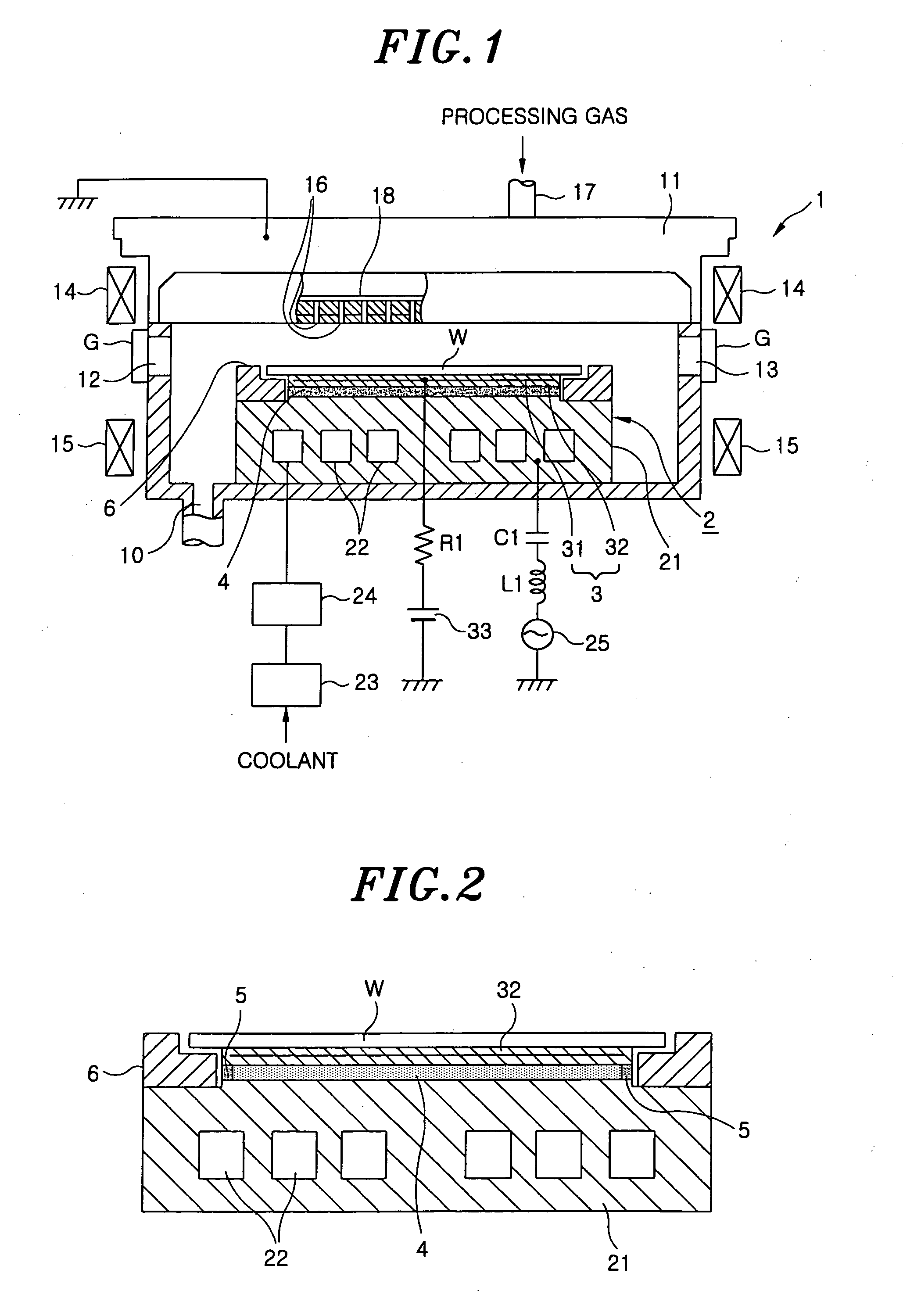
A first embodiment of a processing apparatus in accordance with the present invention is described with reference to FIGS. 1 and 2. FIG. 1 is a longitudinal section showing an entire construction of an example of an etching apparatus that is a processing apparatus of the present embodiment. In this drawing, reference numeral 1 designates a vacuum chamber making up a processing vessel, and is made of, e.g., aluminum to form an airtight structure. In the vacuum chamber 1, an upper electrode 11, also functioning as a gas showerhead (process gas supply unit), and a susceptor 2, also functioning as a lower electrode, are mounted opposite to face each other, and a gas exhaust port 10 is formed in the bottom of the vacuum chamber 1 to communicate with a vacuum pump (not shown). Openings 12 and 13 are formed in the sidewalls of the vacuum chamber 1 to carry in and out a semiconductor substrate, for example, a wafer W, and can be selectively opened and closed by gate valve...
second embodiment
(Second Embodiment)
Another embodiment of the present invention is described below. FIG. 6 is views showing a susceptor 7 used in the present embodiment. The other parts of the processing apparatus (etching apparatus) of the present invention are identical with those of FIG. 1. In FIGS. 2 and 6, the same numerals designate the same parts. A junction layer 70 is used to bond together an electrostatic chuck layer 3 and a support 21, and is made of, for example, a silicone-based adhesive. A soft coating member 71 is placed around the side circumferential surface of the junction layer 70 to protect the junction layer 70 against active species generated by the plasma, for example, fluoric radicals or fluoric ions. As shown in FIG. 6B that is a partially enlarged view of FIG. 6A, a thermally sprayed coating 72 is formed along the circumferential portion of the central portion of the upper surface of the support 21, that is, a protrusion bonded to the electrostatic chuck layer 3. The therm...
third embodiment
(Third Embodiment)
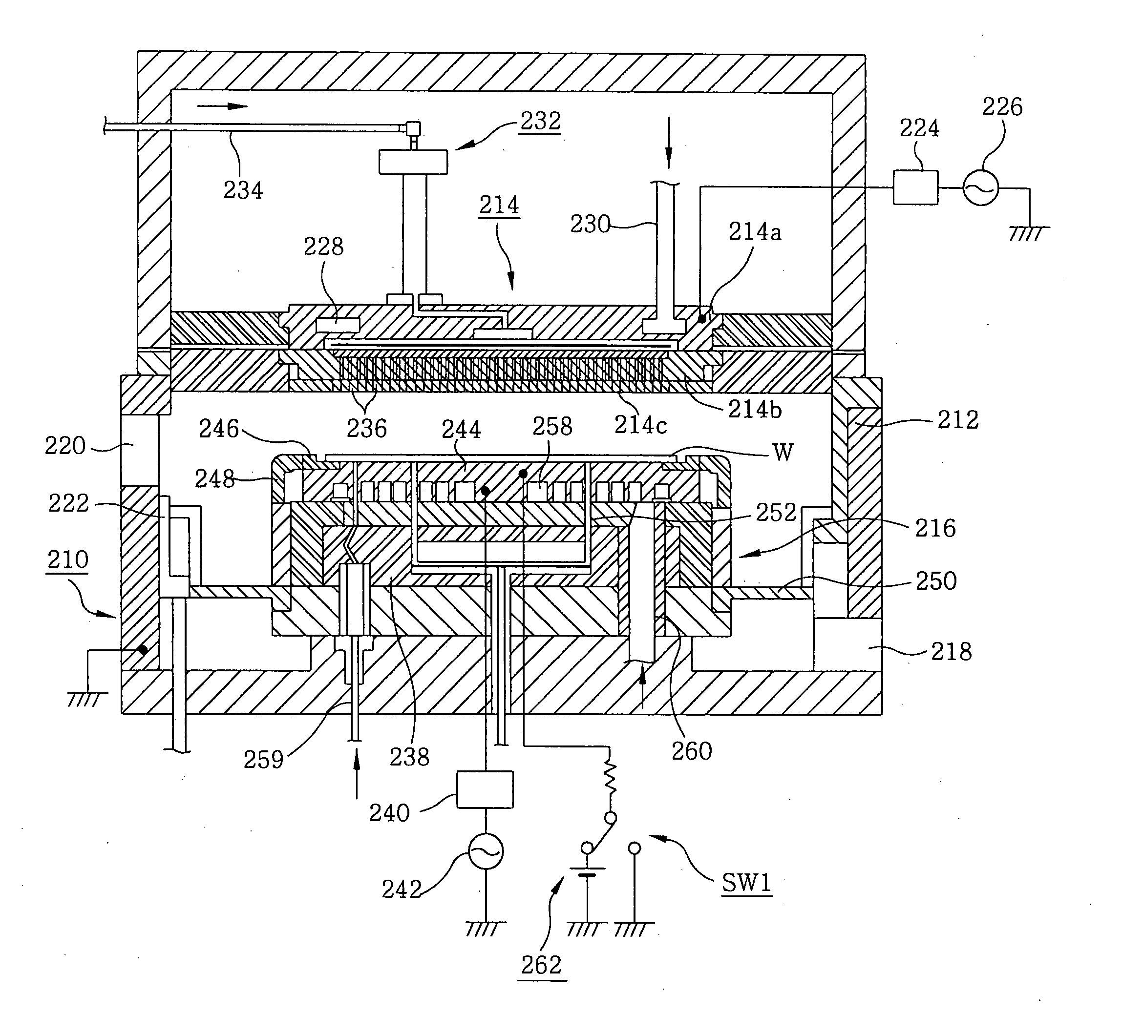
A third embodiment of the present invention is described below. FIG. 9 is a longitudinal section showing an entire structure of an etching apparatus with a plasma apparatus, which is a processing apparatus related to the practice of the invention, applied thereto. In FIG. 9, reference numeral 120 designates a processing vessel that is made of a conductive material, such as aluminum, and is air-tightly sealed. The processing vessel 120 is grounded. In the processing vessel 120, an upper electrode 130, which also functions as a gas shower head that is a gas supply unit for introducing a process gas, and a susceptor 140, which is used to mount a wafer W and also functions as a lower electrode, are placed opposite to face each other. A gas exhaust pipe 121 is connected to the bottom of the processing vessel 120, and vacuum exhaust means, such as a turbo molecular pump or dry pump, is connected to the gas exhaust pipe 121. An opening 123, which is provided with a selec...
PUM
 Abstract
Description
Claims
Application Information