Ffe array dispenser
- Summary
- Abstract
- Description
- Claims
- Application Information
AI Technical Summary
Benefits of technology
Problems solved by technology
Method used
Image
Examples
first embodiment
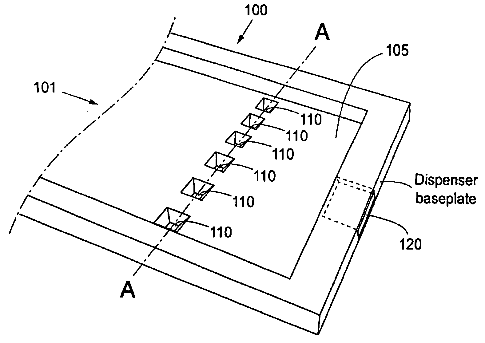
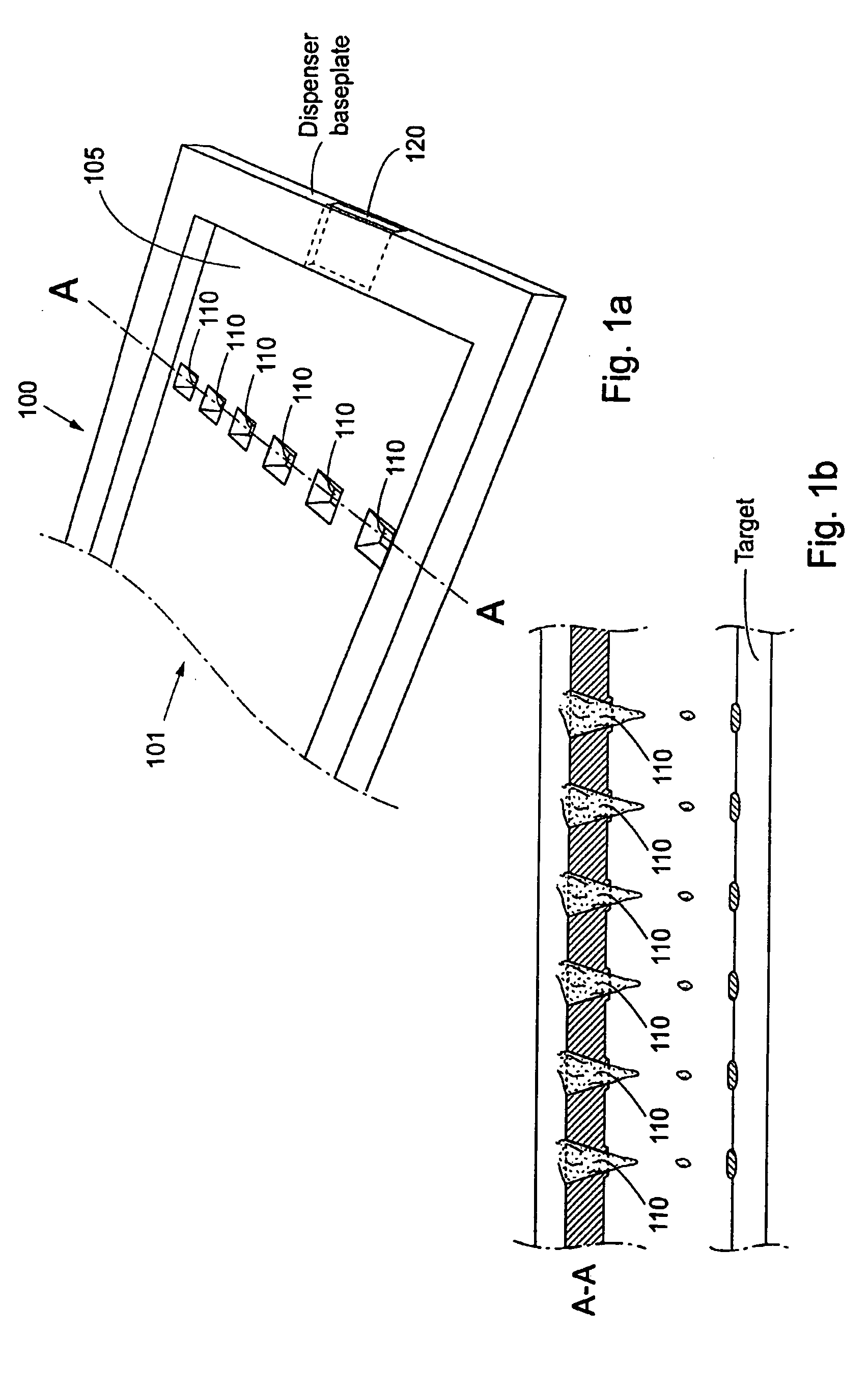
Referring to FIG. 1a, an array 100 according to the present invention comprise one inlet 101 having a rectangular cross section, one pressure cavity 105 having a number of dispenser nozzles 110, said pressure cavity 105 being arranged in fluid communication with said inlet 101. Said pressure cavity 105 also being provided with an outlet 120, different from said nozzles, also arranged in fluid communication with said pressure cavity 105. Said outlet having a rectangular cross section. Each dispenser nozzle 110 is arranged in fluid connection with said cavity 105, and a flexible membrane 130 (FIG. 1c) is arranged as a defining surface of said pressure chamber / cavity 105, such that when the membrane 130 is actuated by a force in a certain direction, the pressure in the cavity rises and an amount of liquid is dispensed through the dispenser nozzle. This embodiment has the advantage that there is no need for separating walls, separating possible parallelly flowing different fractions of ...
second embodiment
Referring to FIG. 2, an array dispenser according to the present invention comprise a number of inlets 103, a number of pressure cavities 104 each having a dispenser nozzle 113, each of said pressure cavities being arranged in fluid communication with a corresponding inlet 103. Said pressure cavity 104 also being provided with an outlet 107, different from said nozzle, also arranged in fluid communication with said pressure cavity 104. Said outlet having a rectangular cross section. Each dispenser nozzle 113 is arranged in fluid connection with said corresponding cavity 104, and a flexible membrane 130 is arranged as a defining surface of said pressure chamber 104, such that a liquid can be supplied via the inlets 103 and dispensed through the dispenser nozzles 113, when the membrane 130 is actuated by a force in a certain direction, thereby forcefully rising the pressure in the cavity 104 such that an amount of liquid is dispensed. The outlets 107 provides the dispenser with flow-t...
fourth embodiment
In a fourth embodiment, referring to FIG. 6, the dispenser comprises an integrated unit 600 comprising a free flow electrophoresis section 601 and a free flow dispenser section 602.
Actuation Force Distribution
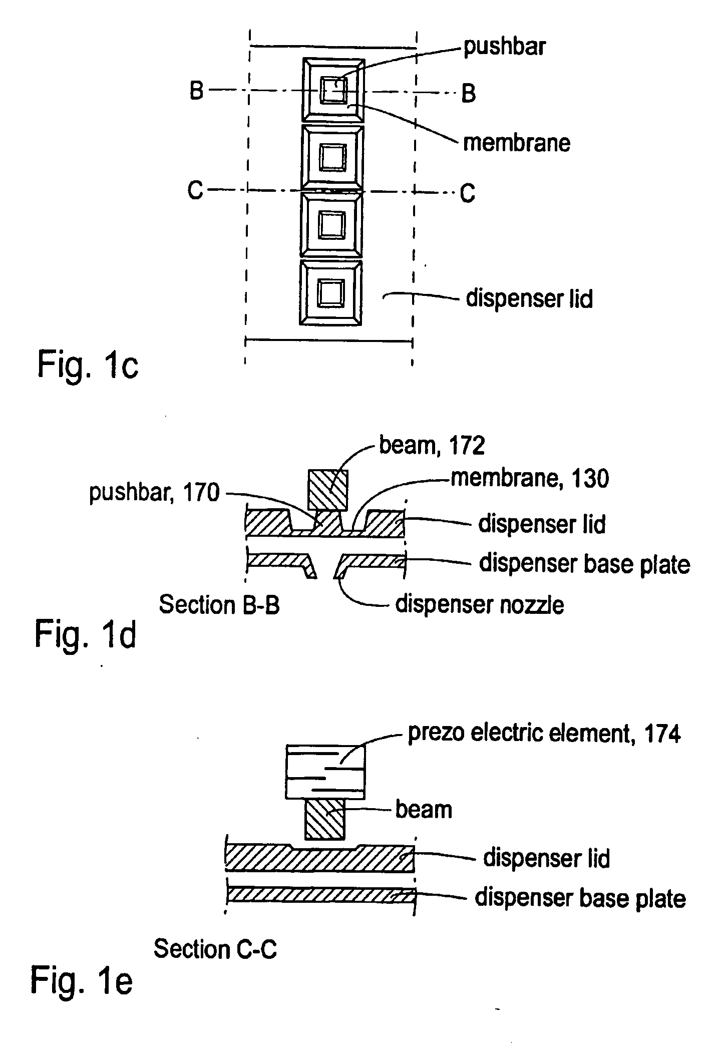
A dispenser array according to an embodiment of the invention preferrably is built up from two plates, a base plate and a lid plate bonded together. The dispenser nozzle array comprises a chamber 501, see FIG. 6, in the base plate, having at least one inlet and at least two dispenser nozzles, and a membrane entity in the lid comprising at least one flexible membrane, and at least one pushbar 170 connected via a beam 172 to a single piezoelectric element 174 capable of providing an actuation force for actuating the membrane entity, and thereby dispensing droplets of liquid through said at least two nozzles simultaneously.
In another embodiment of the invention each pushbar is connected to an individual actuation element fascilitating individual actuation of each pushbar. In ...
PUM
| Property | Measurement | Unit |
|---|---|---|
| Flexibility | aaaaa | aaaaa |
Abstract
Description
Claims
Application Information
 - R&D
- Intellectual Property
- Life Sciences
- Materials
- Tech Scout
- Unparalleled Data Quality
- Higher Quality Content
- 60% Fewer Hallucinations
Browse by: Latest US Patents, China's latest patents, Technical Efficacy Thesaurus, Application Domain, Technology Topic, Popular Technical Reports.
© 2025 PatSnap. All rights reserved.Legal|Privacy policy|Modern Slavery Act Transparency Statement|Sitemap|About US| Contact US: help@patsnap.com


