Dual locking plate and associated method

a double-locking plate and associated technology, applied in the field of double-locking plates, can solve the problems of long bone trauma, complex devastating fractures, automobile accidents, etc., and achieve the effects of promoting bone growth, improving blood flow and healing, and promoting bone growth

Inactive Publication Date: 2005-03-03
DEPUY PROD INC
View PDF61 Cites 203 Cited by
  • Summary
  • Abstract
  • Description
  • Claims
  • Application Information

AI Technical Summary

Benefits of technology

[0023] Another technical advantage of the present invention is that the surgeon may interoperatively or in situ in the patient replace a fastener that has become stripped in the fracture repair system with a larger screw and maintain the rigid securement of the plate. For example, according to one aspect of the present invention, the fracture repair system includes a bone plate that has a threaded hole on the body of the bone plate. The fracture repair system further includes a first fastener which has threads on the cap portion of the fastener as well as small cortical threads on the stem portion of the fastener. If the bone mating with the cortical threads on the stem portion of the fastener becomes stripped, the first fastener may be removed from the bone plate and a second larger fastener, which has a threaded portion on the cap portion of the larger fastener with threads identical to that of the smaller fastener as well as cancellous larger threads on the stem portion of the second larger fastener. Thus, the present invention provides for interoperative use of a larger screw with rigid securement of the plate if the bone mating with the first installed smaller screw is stripped.
[0024] Yet another advantage of the present invention is that the bone fragments separated by trauma may be reconnected. For example, according to one aspect of the present invention, the fracture repair system of the present invention may include a plate having holes into which lag screws may be fitted. The fracture repair system further may include a lag screw or a screw having a portion of the stem void of threads. If the first bone fragment is connected to the head of the fastener and the second bone fragment is connected to the threaded portion of the lag screw as the lag screw is rotated, the bone fragments may be connected or drawn together. Thus, the present invention provides for the connection of separated bone fragments and resulting improvement of blood flow and healing.
[0025] The technical advantages of the present invention further include the ability to position a screw in a divergent direction diverging from the bone plate so that distal condyles and fragments thereof may be properly secured by the bone screw. For example, according one aspect of the present invention, a fracture repair system is provided which includes a bone plate with a cooperating bushing having a spherical per

Problems solved by technology

These long bones are particularly exposed to trauma from accidents and as such often are fractured during such trauma and may be subject to complex devastating fractures.
Automobile accidents for instance are a common cause of trauma to long bones.
In particular the femur and tibia frequently fracture when the area around the knee is subjected to a frontal automobile accident.
Such fractures in the distal or proximal condyle portions of the long bone may result in many individual fragments which must be reconnected.
Thus often the optimum position of a screw may not be utilized as it does not conform to a position nominal or perpendicular to the bone plate.
Two dimensional bone plates do not provide for the optimum diverging orientation of the bone screws.
Further, the use of a non-locking fastener results in increased flexion on motion between the fasteners and the plate thereby increasing the stress or load on the fracture site.
Such increase in fracture load or bracing of the stress adjacent to fracture site results in hypertrophy or the increase in size of the cortical bone due to the physical activity to accommodate the higher stress.
For example, if t

Method used


Image

  • Dual locking plate and associated method
  • Dual locking plate and associated method
  • Dual locking plate and associated method

Examples


Embodiment Construction

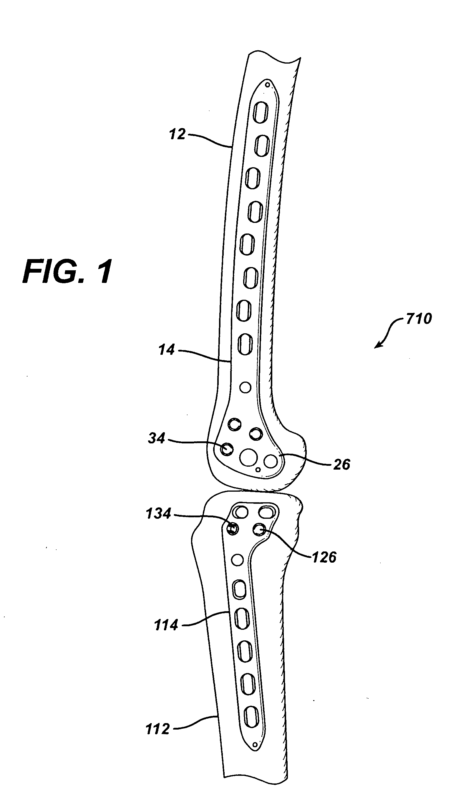
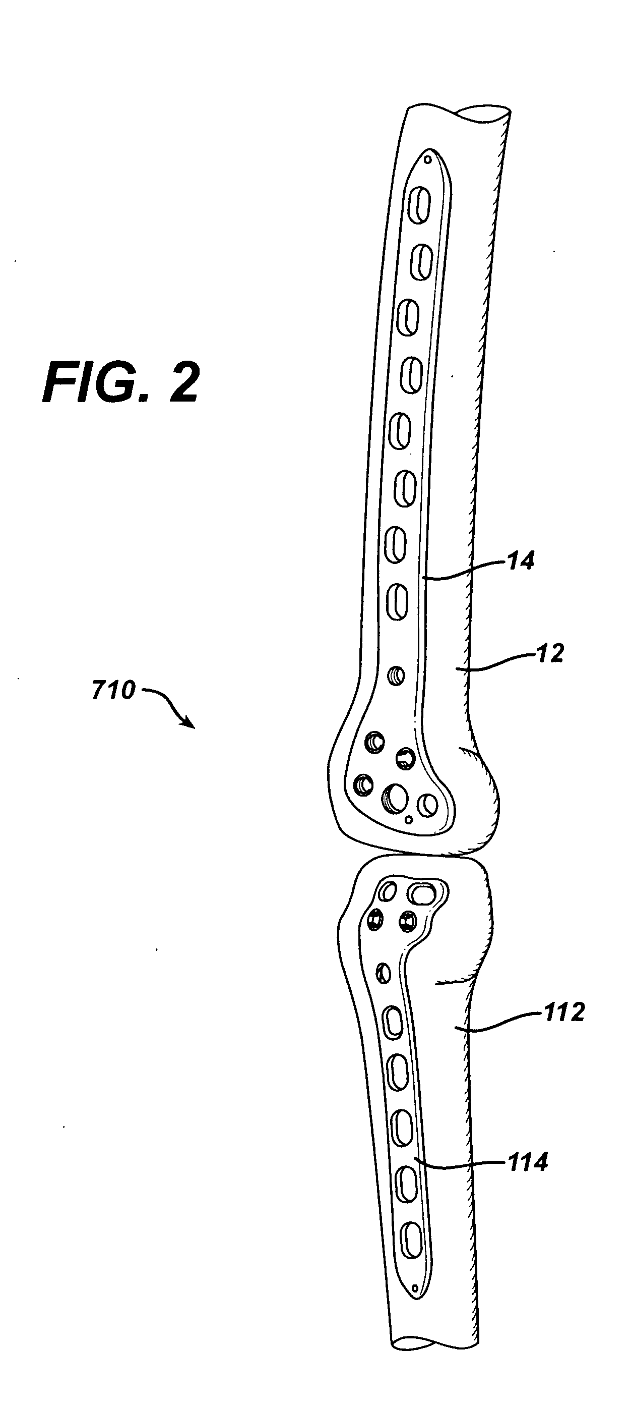
[0109] According to the present invention and referring now to FIG. 6, a fracture repair system 10 is shown for engagement with a long bone 12. The long bone 12 may be any long bone, for example, a femur, tibia, fibula, humerus, radius or ulna, but as shown in FIG. 1 the long bone is a femur. The fracture repair system 10 includes a plate 14.

[0110] Referring now to FIG. 4 the fracture repair system 14 is shown in greater detail. The plate 14 may be made of any suitable durable material and may, for example, be made of a metal, for example, a metal compatible with the human anatomy, for example, cobalt chrome, stainless steel or titanium. The plate 14 includes a body portion 16 and an interior wall 20. The interior wall 20 defines a plate hole 22 through the body portion 16.

[0111] Referring now to FIG. 12 the fracture repair system 10 is shown in greater detail. In addition to the plate 14 the fracture repair system 10 includes one or more bushings 24. The bushing 24 includes a rad...


PUM


Abstract

A system for percutaneous fracture repair of a bone is provided. The system includes a plate having a first feature and a second feature. The first feature and the second feature are spaced apart from each other. The plate defines a longitudinal axis of the plate. The system also includes a first attachment component operably associated with the first feature. The first attachment component cooperates with the bone. The system also includes a second attachment component operably associated with the second feature. The second attachment component is percutaneously inserted into the second feature. The second attachment component is operably associated with the plate to provide a compressive force in the bone. The compressive force has a component of the force in the longitudinal axis. The second attachment component is adapted for cooperation with the bone.

Description

CROSS REFERENCE TO RELATED APPLICATIONS [0001] This application is a Continuation-in-Part of attorney docket number DEP 673CIP filed Aug. 1, 2003, entitled POLYAXIAL LOCKING PLATE. DEP 673CIP is a Continuation-in-Part of U.S. patent application Ser. No. 10 / 100,387 filed Mar. 18, 2002, entitled POLYAXIAL LOCKING PLATE. U.S. patent Application Ser. No. 10 / 100,387 is a Utility Application based upon U.S. Provisional Patent Application, Ser. No. 60 / 285,462 filed Apr. 20, 2001, entitled POLYAXIAL LOCKING PLATE. DEP 673CIP filed Aug. 1, 2003, entitled POLYAXIAL LOCKING PLATE and U.S. patent application Ser. No. 10 / 100,387 filed Mar. 18, 2002 entitled POLYAXIAL LOCKING PLATE are incorporated by reference herein in their entirety.BACKGROUND OF THE INVENTION [0002] The present invention relates to a bone locking plate, more particularly the present invention relates to a bone locking plate that includes an adjustable attachment component. Most particularly, the present invention relates to a...

Claims


Application Information

Patent Timeline
IPC IPC(8): A61B17/17A61B17/80A61B17/86
CPCA61B17/1728A61B17/8047A61B17/8625A61B17/8061A61B17/8605A61B17/8057
Inventor WACK, MICHAEL A.GUZMAN, PAMELA C.STOLLER, DENNIS A.BREMER, CHRISTOPHER K.OBERST, REBECCA D.FENTON, MARK A.HAIDUKEWYCH, GEORGE J.BONE, LAWRENCE B.SANDERS, ROY W.
Owner DEPUY PROD INC
Why Eureka
Try Eureka