Tissue distention device and related methods for therapeutic intervention
- Summary
- Abstract
- Description
- Claims
- Application Information
AI Technical Summary
Benefits of technology
Problems solved by technology
Method used
Image

Examples
example 1
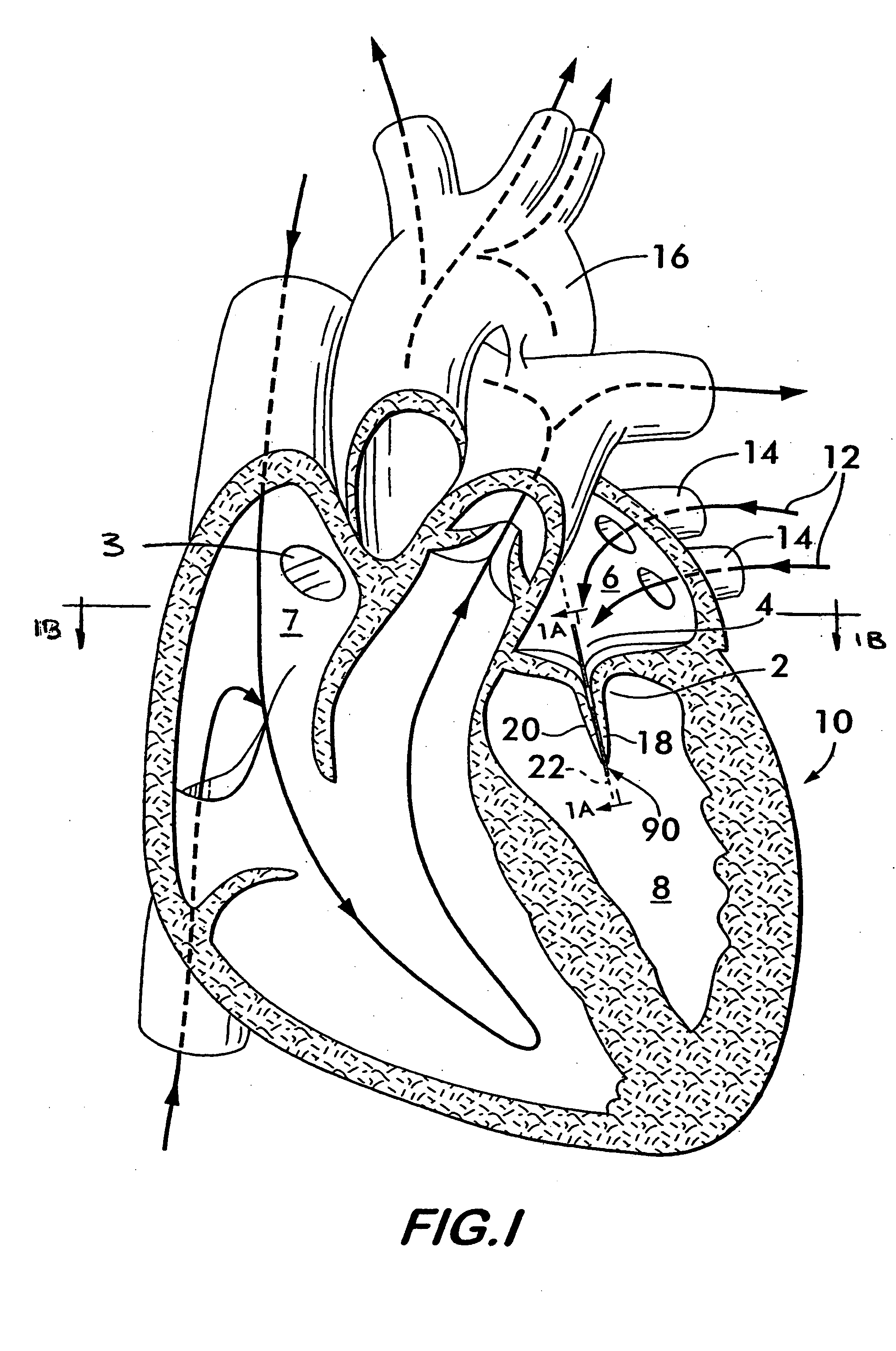
[0092] Mitral Valve Repair
[0093]FIG. 16 shows biasing device 90 contained within shroud 190 in the form of sleeve 198 in a resiliently deformed configuration with leg segments 112, 122 and 132 positioned proximally to leg segments 114, 124 and 134 allowing device 90 to fit within and slide through a lumen 164 of a catheter 166. Device 90 is resiliently biased to assume the configuration shown in FIG. 8 with the leg segments 112, 114 and 132 in spaced relation to the leg segments 114, 124 and 134. Device 90 will assume this spaced apart configuration upon release from catheter 166, the catheter providing the restraining force to keep the leg segments in the resiliently deformed, proximal configuration. These resilient characteristics of the device allow it to be transported through the vascular system via the catheter to the position where it is to be implanted without the need for traumatic, invasive surgery. The device according to the invention is then released from the catheter ...
example 2
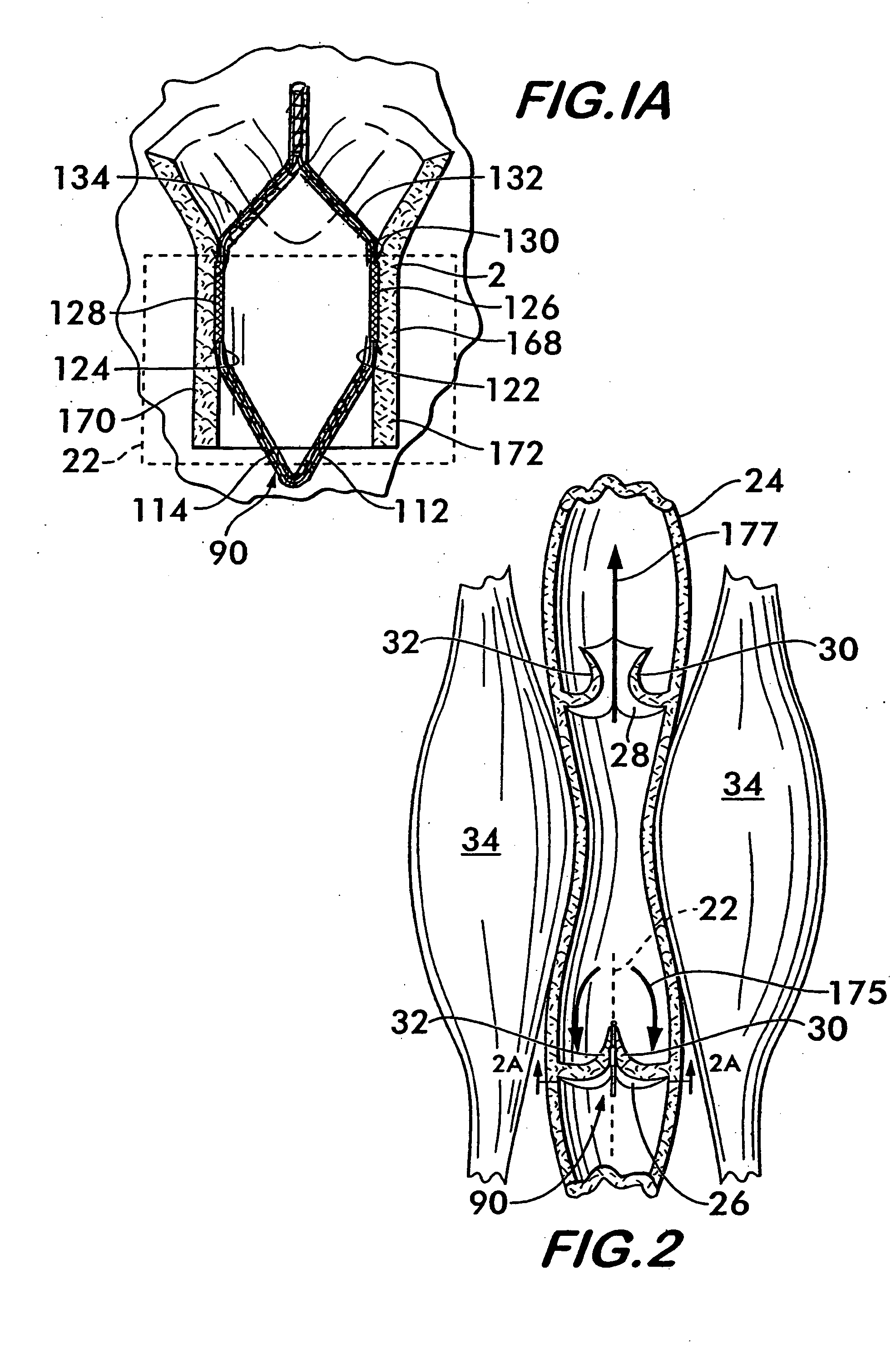
[0095] Venous Valve Repair
[0096]FIGS. 2 and 2A show a biasing device 90 according to the invention implanted in a vein 24 to effect repair of an incontinent venous valve 26. Similar to the repair of the mitral valve, the device 90 is deployed from catheter 166 (see FIG. 10) within the vein 24 with its leg segments coplanar with the plane 22 of the valve 26. As shown in FIG. 2A, opposing portions 174 and 176 of the vein 24 at the valve leaflets 30 and 32 are engaged by the anchoring substrates 126 and 128 to bias the opposing vein portions outwardly thereby drawing valve leaflets 30 and 32 inwardly toward one another in a direction perpendicular to the plane 22 of the valve 26. As shown in FIG. 2, by positioning the leaflets 30 and 32 in closer proximity they are more likely to seal effectively when back pressure, as indicated by arrows 175, is applied within vein 24 by muscles 34. With the otherwise incontinent valve 26 repaired, blood is forced to flow through the vein 24 in the d...
example 3
[0097] Repair of Saccular Aneurysm
[0098]FIGS. 3 and 3A show device 90 positioned in a saccular aneurysm 36. Device 90 is deployed from a catheter to position its anchoring substrates 126 and 128 at the neck 46 of the aneurysm 36. The anchoring substrates 126 and 128 engage opposing portions 178 and 180 of the neck 46 and bias them outwardly, thereby drawing opposite neck portions 182 and 184 toward one another perpendicular to the plane of the device 90. The biasing action of the device 90 on the neck 46 of aneurysm 36 constricts the neck as shown in FIG. 3 and reduces the flow of blood into the aneurysm, reducing pressure on the dome 48 and providing a stagnant region at the neck 46 which will encourage clotting and eventually seal off the aneurysm, thereby preventing its rupture. Preferably, device 90 has the shroud embodiment 188 which comprises the single central layer 196. Central layer 196 provides a matrix into which cells from the opposing neck portions 182184 may grow to p...
PUM
 Abstract
Description
Claims
Application Information
 - R&D Engineer
- R&D Manager
- IP Professional
- Industry Leading Data Capabilities
- Powerful AI technology
- Patent DNA Extraction
Browse by: Latest US Patents, China's latest patents, Technical Efficacy Thesaurus, Application Domain, Technology Topic.
© 2024 PatSnap. All rights reserved.Legal|Privacy policy|Modern Slavery Act Transparency Statement|Sitemap