Capacity control valve for variable displacement compressor

Inactive Publication Date: 2005-03-10
TGK
View PDF7 Cites 13 Cited by
  • Summary
  • Abstract
  • Description
  • Claims
  • Application Information

AI Technical Summary

Benefits of technology

[0015] The present invention has been made in view of the above-described points, and an object thereof is to provide a capacity control valve for a variable displacement compressor, which su

Problems solved by technology

A compressor used for compressing refrigerant in a refrigeration cycle of an automotive air conditioner is driven by an engine, which makes it impossible to perform rotational speed control of the compressor.
However, the variable displacement compressor using the conventional capacity control valve, characteristics of which are illustrated in FIG. 8, suffers from the problem that when the current (solenoid current) supplied to the solenoid is stepwise changed, the pressure Pc in the crankcase is largely changed according to a change in the solenoid current, which causes a large chang

Method used


Image

  • Capacity control valve for variable displacement compressor
  • Capacity control valve for variable displacement compressor
  • Capacity control valve for variable displacement compressor

Examples


second embodiment

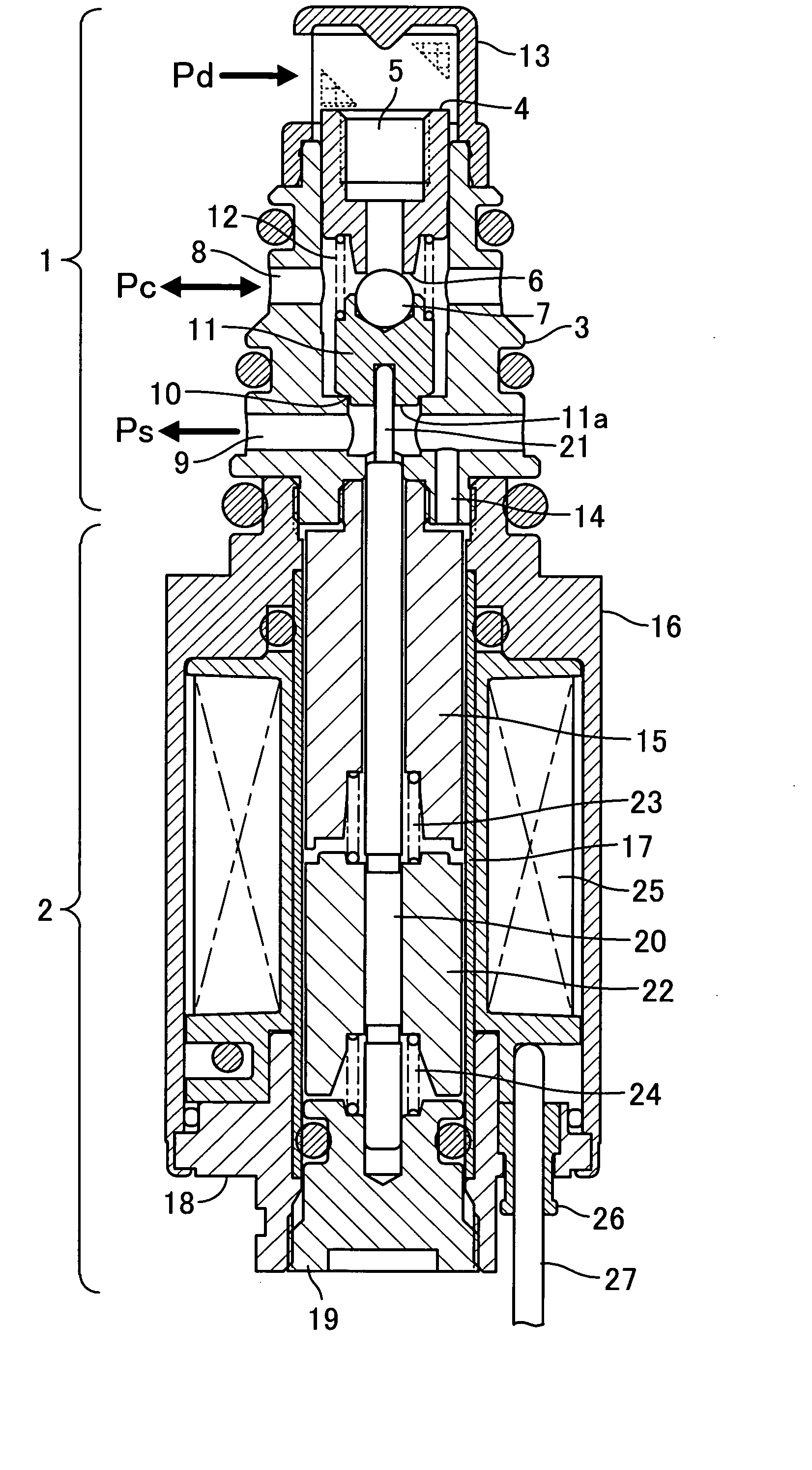
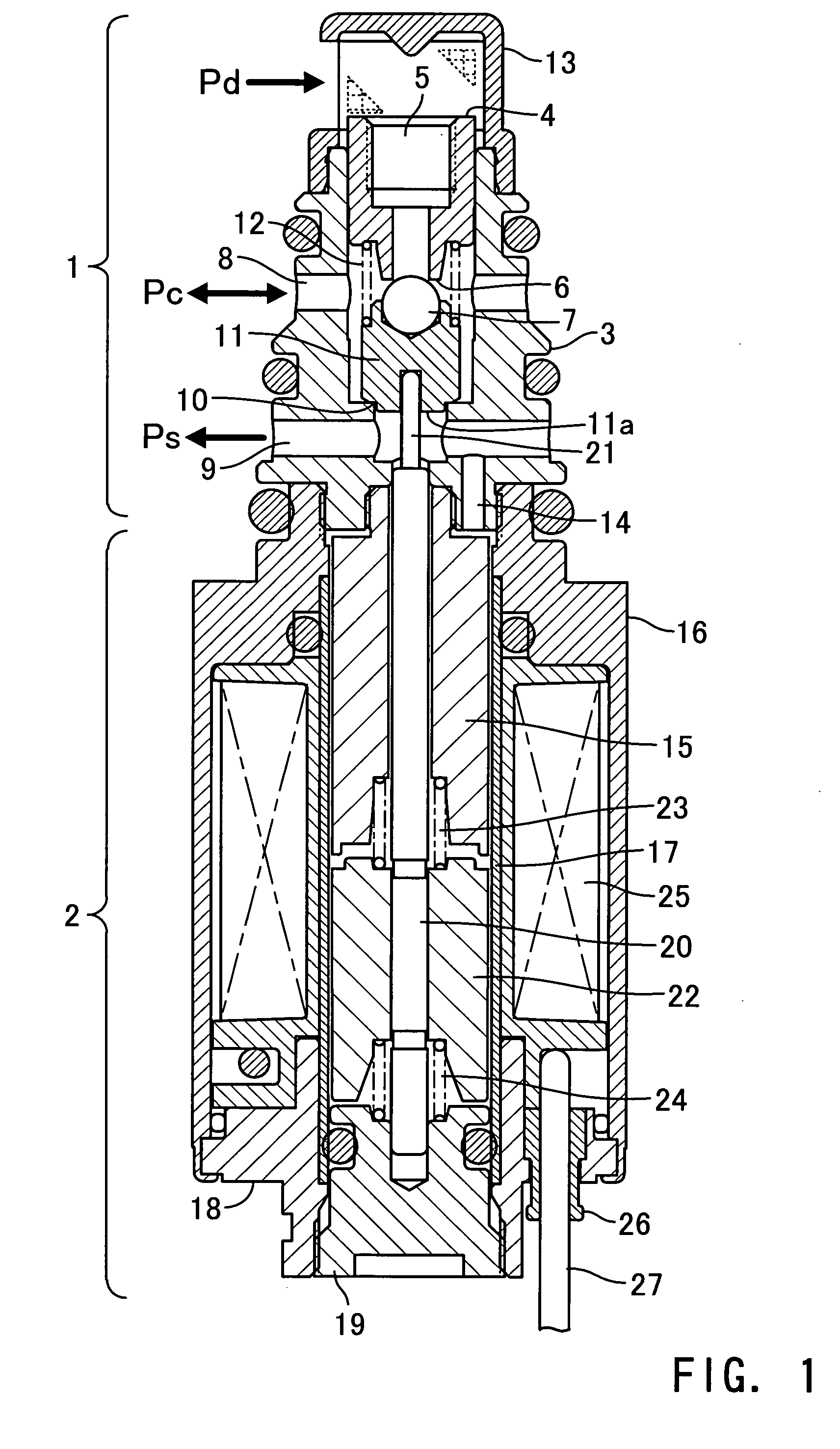
[0041]FIG. 4 is a central longitudinal cross-sectional view showing a capacity control valve according to the invention. In FIG. 4, component elements identical to those in FIG. 1 are designated by identical reference numerals, and detailed description thereof is omitted.

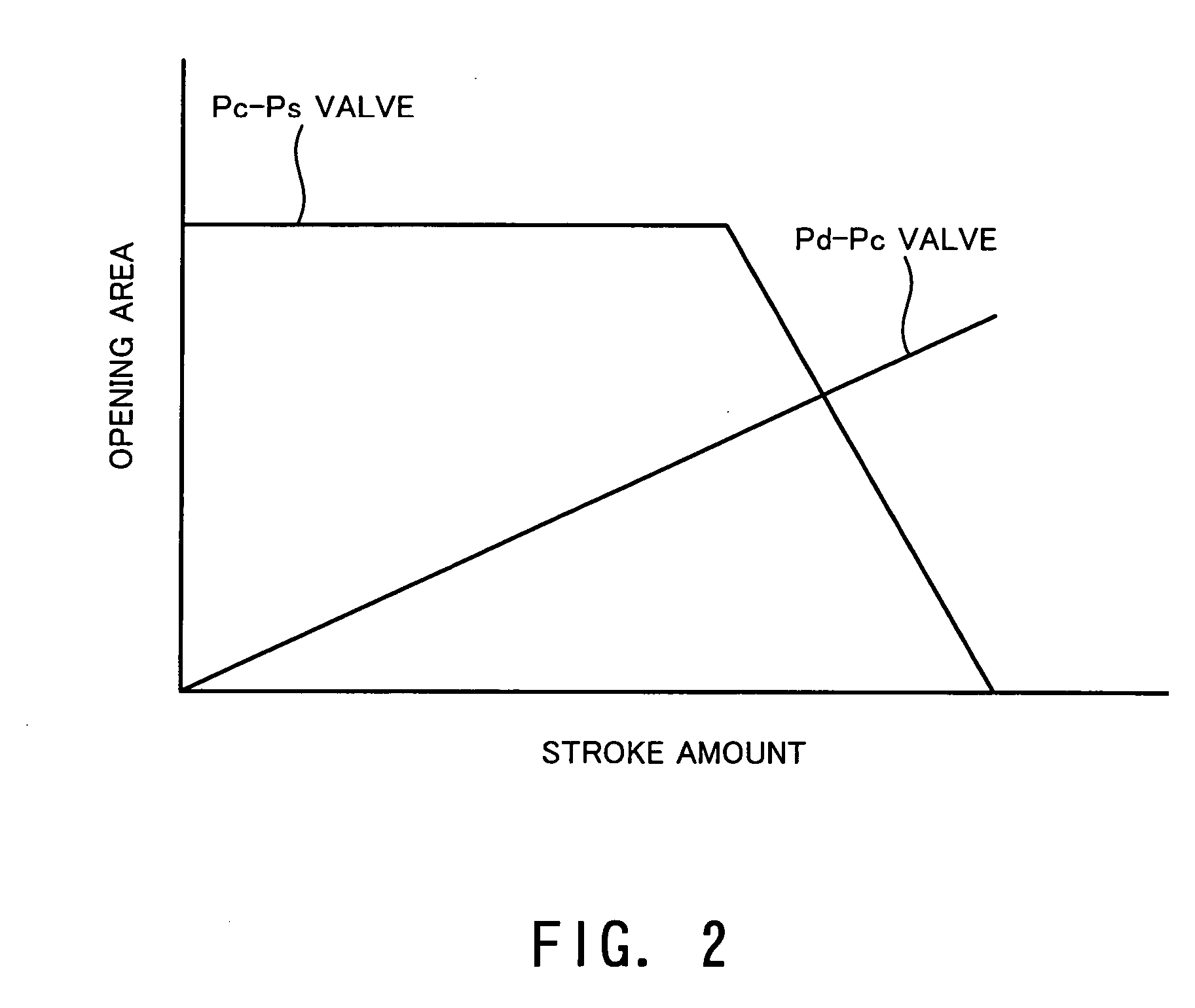
[0042] Although the capacity control valve according to the first embodiment attains the flat characteristic of the Pc-Ps valve by the spool valve structure, the capacity control valve according to the second embodiment attains the same by providing an orifice 28 as flow rate-restricting means whose opening area does not change.

[0043] That is, the Pc-Ps valve has a valve element 11 whose surface opposed to the valve seat 10 is formed to have a tapered shape, and the orifice 28 is provided between the downstream side of the valve element 11, and the port 9 and the passage 14. The orifice 28 is disposed in series with the Pc-Ps valve, and therefore, when the opening area of the Pc-Ps valve becomes larger than the ope...

third embodiment

[0044]FIG. 5 is a central longitudinal cross-sectional view showing a capacity control valve according to the invention. In FIG. 5, component elements identical to those in FIG. 1 are designated by identical reference numerals, and detailed description thereof is omitted.

[0045] Compared with the capacity control valve according to the first embodiment shown in FIG. 1, the capacity control valve according to the third embodiment is configured such that the operation of the Pc-Ps valve is not adversely affected by the pressure Pc in the crankcase.

[0046] More specifically, the capacity control valve is provided with a passage 14 which causes a space between the Pd-Pc valve and the Pc-Ps valve, which is connected to the crankcase via the port 8, to communicate with the inside of the solenoid section, whereby the pressure Pc in the crankcase is transmitted to the inside of the solenoid section 2. This causes the valve element 11 of the Pc-Ps valve to receive the pressure Pc in the crank...

fourth embodiment

[0049]FIG. 6 is a central longitudinal cross-sectional view showing a capacity control valve according to the invention. In FIG. 6, component elements identical to those in FIG. 4 are designated by identical reference numerals, and detailed description thereof is omitted.

[0050] Compared with the capacity control valve according to the second embodiment shown in FIG. 4, the capacity control valve according to the fourth embodiment is configured such that the operation of the Pc-Ps valve thereof is not adversely affected by the pressure Pc in the crankcase.

[0051] More specifically, the capacity control valve is provided with a passage 14 which causes space between the Pd-Pc valve and the Pc-Ps valve connected to the crankcase via the port 8 to communicate with the inside of the solenoid section, whereby similarly to the capacity control valve according to the third embodiment, the pressure Pc in the crankcase is transmitted to the inside of the solenoid section 2. This causes the pre...


PUM


Abstract

To provide a capacity control valve for a variable displacement compressor of a Pd-Ps differential pressure-controlled type, which suppresses overshooting of the differential pressure between the discharge pressure Pd and the suction pressure Ps which can occur when the differential pressure is changed in response to a stepwise change in the solenoid current. The capacity control valve includes a valve section having a Pd-Pc valve for control of the flow rate of refrigerant flowing from a discharge chamber to a crankcase and a Pc-Ps valve for control of the flow rate of refrigerant flowing from the crankcase to a suction chamber operating in a manner interlocked with the Pd-Pc valve. A spool valve element is provided on a valve element of the Pc-Ps valve, whereby in a stroke region where the Pd-Pc valve is toward the fully-closed position, refrigerant is allowed to pass through the clearance between the spool valve element and the valve hole of the Pc-Ps valve, to cause the Pc-Ps valve to have a characteristic that the opening area thereof does not change in response to a change in stroke. This makes it possible to suppress sharp changes in the pressure Pc in the crankcase due to the existence of the clearance, even if the solenoid current is stepwise sharply changed.

Description

CROSS-REFERENCES TO RELATED APPLICATIONS, IF ANY [0001] This application claims priority of Japanese Application No.2003-312369 filed on Sep. 4, 2003 and entitled “CAPACITY CONTROL VALVE FOR VARIABLE DISPLACEMENT COMPRESSOR” and No. 2003-332652 filed on Sep. 25, 2003, entitled “CAPACITY CONTROL VALVE FOR VARIABLE DISPLACEMENT COMPRESSOR”. BACKGROUND OF THE INVENTION [0002] (1) Field of the Invention [0003] The present invention relates to a capacity control valve for a variable displacement compressor, and more particularly to a capacity control valve for use in a variable displacement compressor that compresses a refrigerant gas in a refrigeration cycle of an automotive air conditioner. [0004] (2) Description of the Related Art [0005] A compressor used for compressing refrigerant in a refrigeration cycle of an automotive air conditioner is driven by an engine, which makes it impossible to perform rotational speed control of the compressor. To overcome the inconvenience, a variable ...

Claims


Application Information

Patent Timeline
IPC IPC(8): B60H1/32F04B27/18F04B49/00F04B49/06
CPCF04B27/1804F04B2027/1813F04B2027/1877F04B2027/1831F04B2027/1854F04B2027/1827
Inventor HIROTA, HISATOSHIKAJIWARA, MORIMITSUYOSHIHIRO, RYOSUKE
Owner TGK
Why Eureka
Try Eureka