Self-stiffened welded wire lath assembly

a technology of welded wire and assembly, applied in the field of building technology, can solve the problems of stucco sag, underside of exposed roof area, difficulty in applying stucco to overhanging surfaces, etc., and achieve the effects of reducing blowing, reducing stress, and being more rigid

Inactive Publication Date: 2005-03-17
SACKS ABRAHAM +4
View PDF13 Cites 30 Cited by
  • Summary
  • Abstract
  • Description
  • Claims
  • Application Information

AI Technical Summary

Benefits of technology

[0026] This invention provides a wire lath that can be made to be more rigid than current wire lath products, provides ...

Problems solved by technology

Difficulties can be encountered in applying stucco to overhanging surfaces such as soffits (i.e. the area under building eaves) and the undersides of exposed roof areas, such as porticos.
In such areas gravity tends to cause the stucco to sag after it has been applied.
If the lath is deflected significantly during installation, then stucco in areas adjacent to the deflected area will be disturbed and will likely fall out.
A stucco layer which is uneven in thickness can be prone to cracking.
The paper helps reduce the amount of plaster waste and is not intended to be moisture resistant.
However, these products have some disadvantages.
First, at the locations of the stiffening ribs, the stucco is much thinner than it is at other locations.
Furthermore, the ribs present unbroken surfaces which do not provide opportunity for embedment and keying of stucco.
This typically results in a series of cracks forming along each of the ribs.
Another disadvantage of prior expanded metal lath systems is that the keys are typically quite small.
However, with small key openings it is difficult to force stucco adequately through the lath in the overlapping portions.
This results in a weak zone in which the stucco is likely to crack at each point where sheets of the lath overlap.
A third difficulty with expanded metal lath is that it is difficult to cut, especially if the ribs are high.
This makes current expanded metal lath products tedious and even dangerous to install.
However, current paper-backed wire laths have two major disadvantages.
First, the relatively large wire grid spacing provides little hang on surface area for the wet stucco to hang o...

Method used


Image

  • Self-stiffened welded wire lath assembly
  • Self-stiffened welded wire lath assembly
  • Self-stiffened welded wire lath assembly

Examples


Embodiment Construction

[0045] Throughout the following description, specific details are set forth in order to provide a more thorough understanding of the invention. However, the invention may be practiced without some of these particulars. In other instances, well known elements have not been shown or described in detail to avoid unnecessarily obscuring the invention. Accordingly, the specification and drawings are to be regarded in an illustrative, rather than a restrictive, sense.

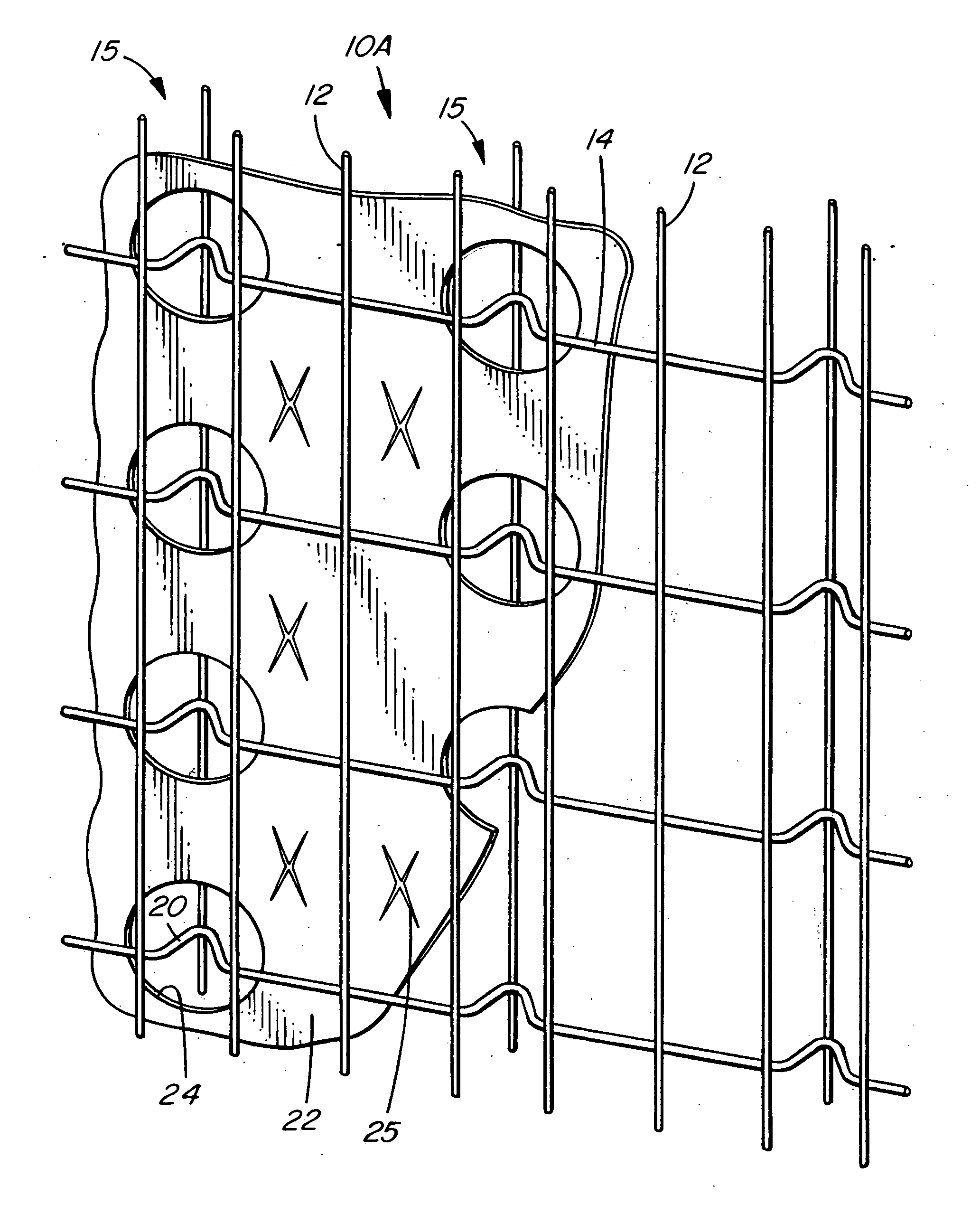
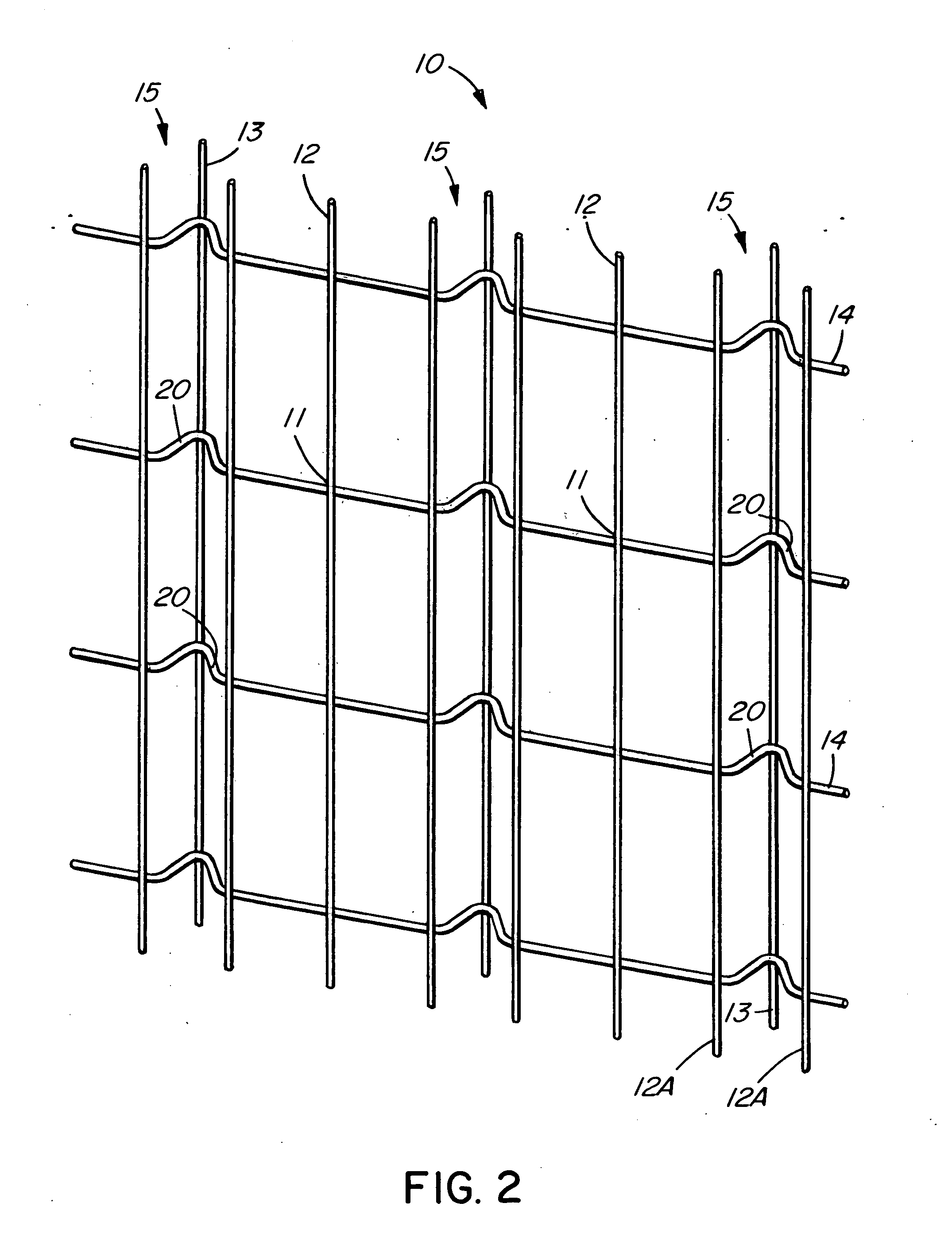
[0046] Referring to FIG. 2 and FIG. 3, lath 10 according to a currently preferred embodiment of the invention comprises a plurality of first generally parallel longitudinal wires 12 which intersect with a plurality of generally parallel transverse wires 14.

[0047] Wires 12 lie substantially in a first plane PI (best appreciated by reference to FIG. 3). Similarly, wires 14 lie substantially in plane PI, save that wires 14 are bent out of plane P1 at truss locations 15.

[0048] Wires 12 and 14 are welded together at their inter...


PUM


Abstract

A self-furring wire lath comprises a mesh of transverse and longitudinal wires welded at their intersections. Stiffening trusses are formed by bent sections in the transverse wires and longitudinal wires attached to the shoulders of the bent sections. A barrier layer material is retained in the lath between the apex of the bent sections and the principal plane of the lath mesh. The barrier layer material has apertures that coincide with the intersections only at the bent sections to enable mesh size reduction without compromising the barrier layer but still allow the fabrication of the lath. The lath provides good embedment in the stucco, reduces cracking and wastage of stucco while remaining easy to work with.

Description

RELATED APPLICATION [0001] This application is a continuation-in-part of U.S. patent application Ser. No. 09 / 927544 titled Self-stiffened welded wire lath assembly by Abe Sacks et al., filed on Aug. 13, 2001.FIELD OF THE INVENTION [0002] This invention relates to building technology, and in particular to wire lath which may be used to reinforce coatings, such as stucco, applied to soffits and other building surfaces. BACKGROUND OF THE INVENTION [0003] Some building construction techniques involve the application of a coating, such as stucco, to a surface. The coating may be desired, for example, to improve appearance, enhance fire resistance or to comply with building or fire codes. In the following disclosure the term “stucco” is used generally to apply to cementitious plasters or gypsum plasters, including stuccos as defined in applicable building codes. [0004] When applying a coating of stucco (or other similar material) it is generally desirable to provide a lath on the surface....

Claims


Application Information

Patent Timeline
IPC IPC(8): E04C5/04E04C5/06E04F13/04
CPCB21F27/20E04C5/04E04F13/045E04F13/04E04F13/047E04C5/0627
Inventor SACKS, ABRAHAMSACKS, JEFFREY L.SPILCHEN, WILLIAMRUGINA, NARCISDAVIS, HAROLD R.
Owner SACKS ABRAHAM
Why Eureka
Try Eureka