Method for producing connecting ends on metal tubes and tube piece comprising such connecting ends

a technology of metal tubes and connecting ends, which is applied in the direction of resistance welding apparatus, curved planar seam welding, application, etc., can solve the problems of inability to further process and reject, and the fixing of burst-open metal layers in the region of burst-open connecting ends is, in particular, not practicable, and requires relatively expensive tools. , to achieve the effect of safe and effective tube welding, safe preventing tearing of the tube piece, and large width

Inactive Publication Date: 2005-03-17
BOA BALG UND KOMPENSATOREN TECH
View PDF9 Cites 3 Cited by
  • Summary
  • Abstract
  • Description
  • Claims
  • Application Information

AI Technical Summary

Benefits of technology

[0014] Undefined overlappings of the layers of such tubes (in particular up to 4 non-uniformly oriented layers) are thereby prevented.
[0015] The inventive method permits extremely rapid and effective welding of the tube in the region of its connecting ends. In a preferred embodiment, a welding seam which extends along the entire periphery of the tube is provided by seam welding to fix the metal layers in the separation region. Only one single welding seam is therefore sufficient for fixing the metal layers of the tube around the entire periphery and may have a considerably larger width than a welding seam produced through laser welding as defined by the width of the roller-shaped welding electrodes. The seam can withstand large loads, in particular, in the axial and also radial directions of the tube.
[0016] Cutting of the tube piece from the correspondingly pretreated tube of larger length or endless tube can be effected in a simple manner through separation in the region of the welding seam produced through seam welding, wherein the welded metal layers of the tube piece are reliably and permanently fixed in the region of the connecting ends thereby safely preventing tearing of the tube piece in the region of the connecting ends. This is also true, in particular, in the event of subsequent widening or calibration processes, wherein relatively large widening of the connecting ends is possible without requiring annealing processes which are necessary in accordance with prior art in order to reverse the strain hardening produced during manufacture of the endless tube. The continuous connection of the metal layers of the tube about the entire periphery using seam welding moreover ensures uniform and regular connection of the individual layers throughout the entire, relatively wide connecting region of the layers such that a later widening or calibration process provides uniform distribution of loads with, in particular, the elimination of load peaks which occur substantially in punctiform or linear laser welding processes. The thermal influence zone of the welding seam thereby extends over the entire width thereof and around the periphery of the tube such that an annealed structure is produced in this region which is favorable for subsequent widening of the tube piece in the region of the connecting ends, while avoiding the need for a separate annealing process. Finally, residual lubricants are eliminated which could be produced by the seam welding process during manufacture of the tube and which could otherwise cause disturbances when welding the tube piece to an exhaust pipe e.g. of an automotive vehicle.
[0017] The width of the welding seam is preferably between approximately 2 mm and 12 mm, in particular, between approximately 3 mm and 8 mm. The welding seam is thereby sufficiently wide to provide simple separation of a tube piece in the region of the welding seam while assuring permanent connection of the metal layers of the separated tube piece in the region of its connecting ends.
[0022] The invention also concerns a tube piece, in particular a wound metal tube piece which comprises several metal layers and at least one connecting end in the region of which at least regions of the overlapping metal layers are welded together. To solve the underlying problem of the invention, the metal layers of such a tube piece are seam welded together in the region of the connecting end over at least part of the periphery of the tube piece. The metal layers are thereby seam welded together throughout a surface area region. The metal layers of the tube piece may thereby be continuously seam welded to each other, preferably in the region of the connecting end and throughout the entire periphery of the tube piece. Such a tube piece provides optimum durability in the region of its connecting ends. In particular, the formation of cracks in the region of its connecting ends is reliably prevented.

Problems solved by technology

This separating process may not be effected by merely cutting perpendicularly to the tube axis, since fixation of neighboring layers would be partially destroyed and the strip end would burst open due to its internal tension leading to sharp tips or triangular protrusions at the strip end.
Should a tube piece have such burst-open connecting ends, it cannot be further processed and must be rejected.
Later fixing of the burst-opened metal layers in the region of the burst-open connecting ends is, in particular, not possible in practice, since the metal layers are exposed to bending loads.
This requires, however, relatively expensive tools which must also be adapted to the respective tube geometry.
Moreover, permanent fixing of the metal layers which would allow, in particular, later widening of the tube piece in the region of the connecting ends as is required for adjustment to the pipe diameter of neighboring pipe elements, is not possible in practice.
One disadvantage is the substantial splashing during the required point welding of very oily and coated metal strips which can soil the processing optics and gas conduits.
This process is time consuming and therefore expensive.
If the welding points have similar separations, there is always the fundamental risk that small residual triangular protrusions or nubs are formed after subsequent cutting off of the tube piece.
The welded stitch seam at the terminating end of the wound tube tends to tear during a subsequent widening or calibration process leading to incomplete fixation in the region of the connecting ends.
It however, also bears the danger that one or more metal layers are torn in the region of the connecting ends, in particular, during later widening or calibration processes of a tube piece produced in this manner.

Method used


Image

  • Method for producing connecting ends on metal tubes and tube piece comprising such connecting ends
  • Method for producing connecting ends on metal tubes and tube piece comprising such connecting ends

Examples


Embodiment Construction

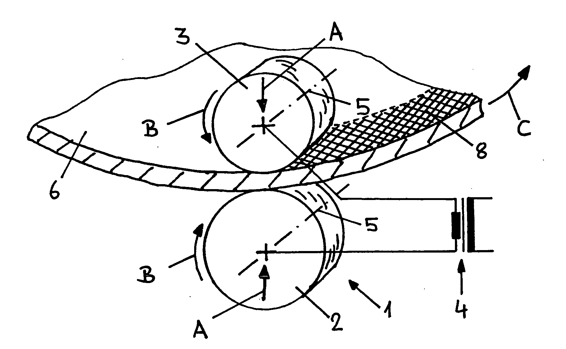
[0030]FIG. 1 shows a schematic view of a seam welding device 1. The device 1 comprises two welding electrodes 2, 3 which are designed as cylinders or rollers and are each loaded with an electric voltage using a welding transformer 4. The welding electrodes 2, 3 are disposed at a mutual separation, and the workpieces which are to be welded together are introduced into the gap provided between the electrodes 2, 3. The electrodes 2, 3 can be loaded in a normal direction with respect to each other (see arrows A) to provide the pressing force required during the welding process. The electrodes 2, 3, which are designed as rollers, are rotatably disposed on their longitudinal central axis 5 and can rotate opposite to each other in the direction of the arrows B. The width of the welding electrodes 2, 3 and of the welding seam which can be produced thereby is e.g. approximately 6 mm.

[0031] In the situation shown in FIG. 1, a metal tube 6 comprising several metal layers (not shown) is insert...


PUM

PropertyMeasurementUnit
widthaaaaaaaaaa
widthaaaaaaaaaa
widthaaaaaaaaaa

Abstract

Connecting ends on a tube piece comprising several metal layers, in particular a wound metal tube piece, are produced by fixing the overlapping metal layers of a tube of larger length or of an endless tube in the region of the point of separation through welding and subsequently cutting off the tube piece from the longer tube or the endless tube. For simple and inexpensive fixing of the metal layers in the region of the point of separation, the invention proposes effecting a welding seam which extends through at least part of the periphery of the tube or about its entire periphery, using seam welding. The tube piece can subsequently be separated along the welding seam obtained in this manner, e.g. along its central line, thereby ensuring permanent and reliable fixing of the metal layers in the region of the connecting end. The invention also concerns a tube piece having a connecting end produced in this manner.

Description

[0001] This application claims Paris Convention priority of DE 103 42 353.2 filed Sep. 12, 2003 the complete disclosure of which is hereby incorporated by reference. BACKGROUND OF THE INVENTION [0002] The invention concerns a method for producing connecting ends on a tube piece having several metal layers, in particular, a wound metal pipe piece, by fixing the overlapping metal layers of a tube having a larger length or of an endless tube in the region of the point of separation through welding to subsequently separate the tube piece from the longer tube or the endless tube. The invention also concerns a tube piece, in particular, a wound metal tube piece which comprises several metal layers and at least one connecting end in the region of which at least regions of the overlapping metal layers are welded together. [0003] Tubes of this type comprising overlapping metal layers are used, in particular in the form of annular or helically wound tubes, as conduit elements in exhaust pipes...

Claims


Application Information

Patent Timeline
Patent Type & Authority Applications(United States)
IPC IPC(8): B23K11/06B23K11/08B23K11/11B23K11/30B23K31/02F16L11/14F16L11/16
CPCB23K11/065B23K2201/06B23K11/3036B23K11/082B23K2101/06
Inventor KERN, EDWARDPONTZEN, MARCGOLEY, STEPHEN
Owner BOA BALG UND KOMPENSATOREN TECH
Why Eureka
Try Eureka