Method and apparatus for thermographic imaging using flash pulse truncation

a thermographic imaging and pulse truncation technology, applied in the field of pulse thermography, can solve the problems of less practical lasers when used to instantaneously heat a large area, the actual spatial temperature distribution at the sample surface may be quite non-uniform, and the surface immediately above the defect to cool at a different rate, so as to achieve the effect of high speed capability and precise control of flash timing characteristics

Inactive Publication Date: 2005-03-17
THERMAL WAVE IMAGING
View PDF9 Cites 54 Cited by
  • Summary
  • Abstract
  • Description
  • Claims
  • Application Information

AI Technical Summary

Benefits of technology

[0020] According to one aspect of the invention, an add-on pulse controller device has been developed that serves as an accessory to popular high-energy flash supplies, such as, for example, Speedtron and BALCAR®. In operation, the add-on pulse controller device truncates thermographic imaging flash duration and adjusts the onset of flash timing to render precise control of flash timing characteristics.
[0021] According to another aspect of the invention, a portable pulsed thermography system is configured to provide high speed capability using a camera operating at the conventional (60 Hz) frame rate. The portable pulsed thermography system addresses the uniformity and duration of the flash illumination, as well as the placement and proximity of the flashlamp, and the method by which data is acquired and processed.

Problems solved by technology

More particularly, subsurface defects cause the surface immediately above the defect to cool at a different rate than that of the surrounding defect-free areas.
In an alternative embodiment, a laser may be employed to heat a surface; however, lasers are less practical when used to instantaneously heat a large area.
Several drawbacks result from the standard practice of using photographic equipment in pulsed thermography NDE.
For example, the direct energy projected onto the sample by the plasma arc is much greater than the indirect energy projected by the reflector, so that the actual spatial temperature distribution at the sample surface may be quite non-uniform, with “hot spots” in the areas where the direct energy of the plasma arc was projected onto the sample.
Invariably, in describing pulsed thermography, the use of a “brief, spatially uniform pulse of light” is mentioned; however, close scrutiny of the current practice employed in pulsed thermography NDE clearly shows that the generated light pulses are neither spatially uniform, nor brief, when considered on the scale of thermal diffusion times.
However, high speed cameras are significantly more expensive and generally require some trade-off in pixel density (i.e. the pixel count must be reduced as the frame rate is increased, in order to maintain operation within a fixed bandwidth limit).
Furthermore, IR cameras can be rendered ineffective by conventional thermal excitation schemes that are widely used because these schemes can cause causes detector saturation or nonlinear camera response (especially in the frames proximate to the excitation by the light pulse).
As a result, true high speed, high resolution pulsed thermography NDE is rarely performed, and can only be done with extremely specialized (and expensive) equipment.
The equipment is large and cumbersome, and does not lend itself to applications where a small portable unit is to be deployed, such as aircraft inspection.
Thus, the afterglow tends to cause the IR camera to saturate or yield a non-linear response.
Although high-speed cameras at frame rates up to 1.5 kHz are commercially available, the performance of these cameras is not well integrated with to the characteristics of the off-the-shelf flashlamps described above.
The duration of the flash and the subsequent tail tends to render the camera “blind” for several frames, so that data that corresponds to “near surface features” is lost.
However, as the temperature approaches ambient, noise effects become more pronounced and the signal to noise ratio decreases.
As a result, it becomes difficult to detect deeper defect features, as weaker signals are masked by noise from the camera electronics or stray reflected radiation.

Method used


Image

  • Method and apparatus for thermographic imaging using flash pulse truncation
  • Method and apparatus for thermographic imaging using flash pulse truncation
  • Method and apparatus for thermographic imaging using flash pulse truncation

Examples


Embodiment Construction

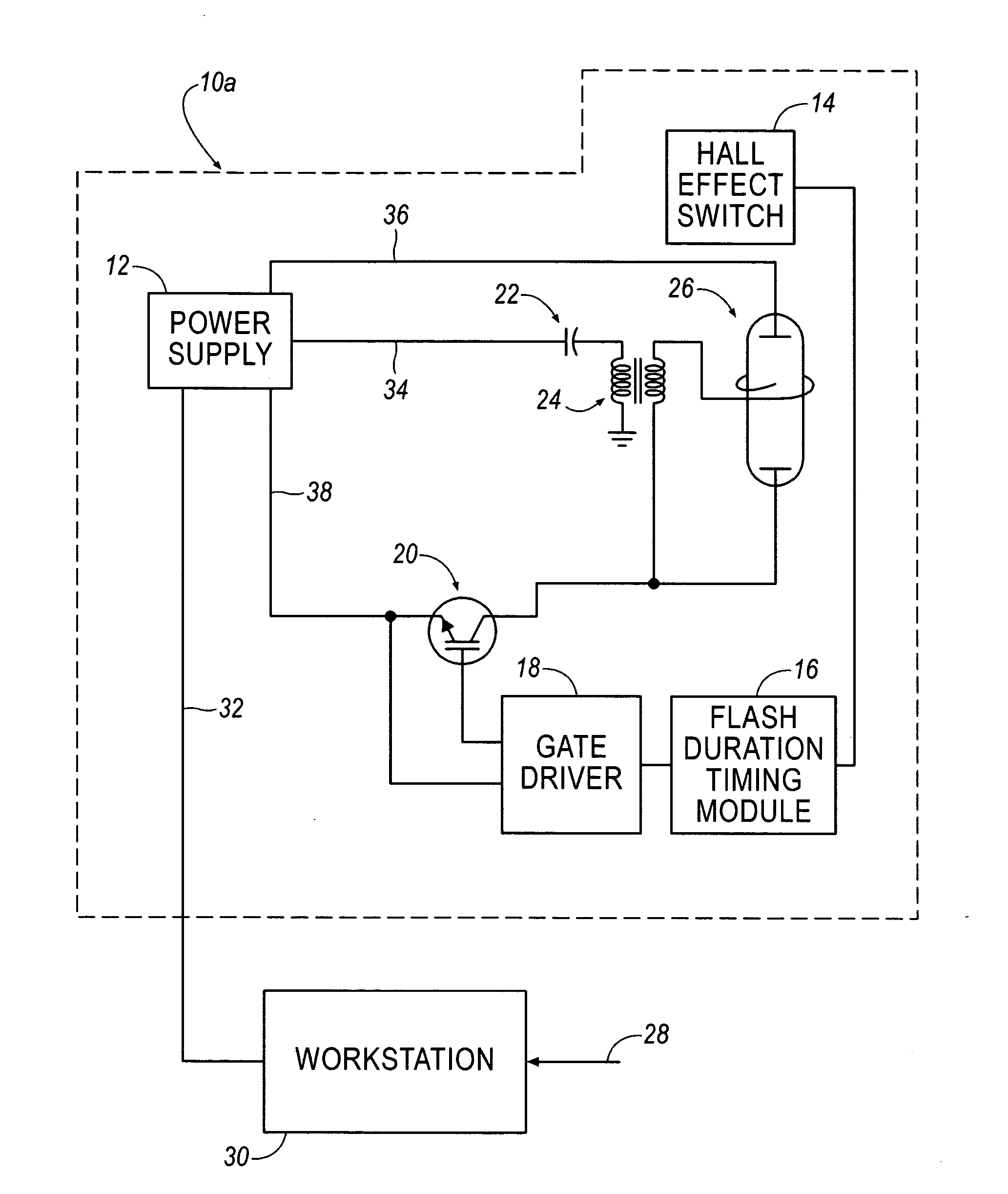
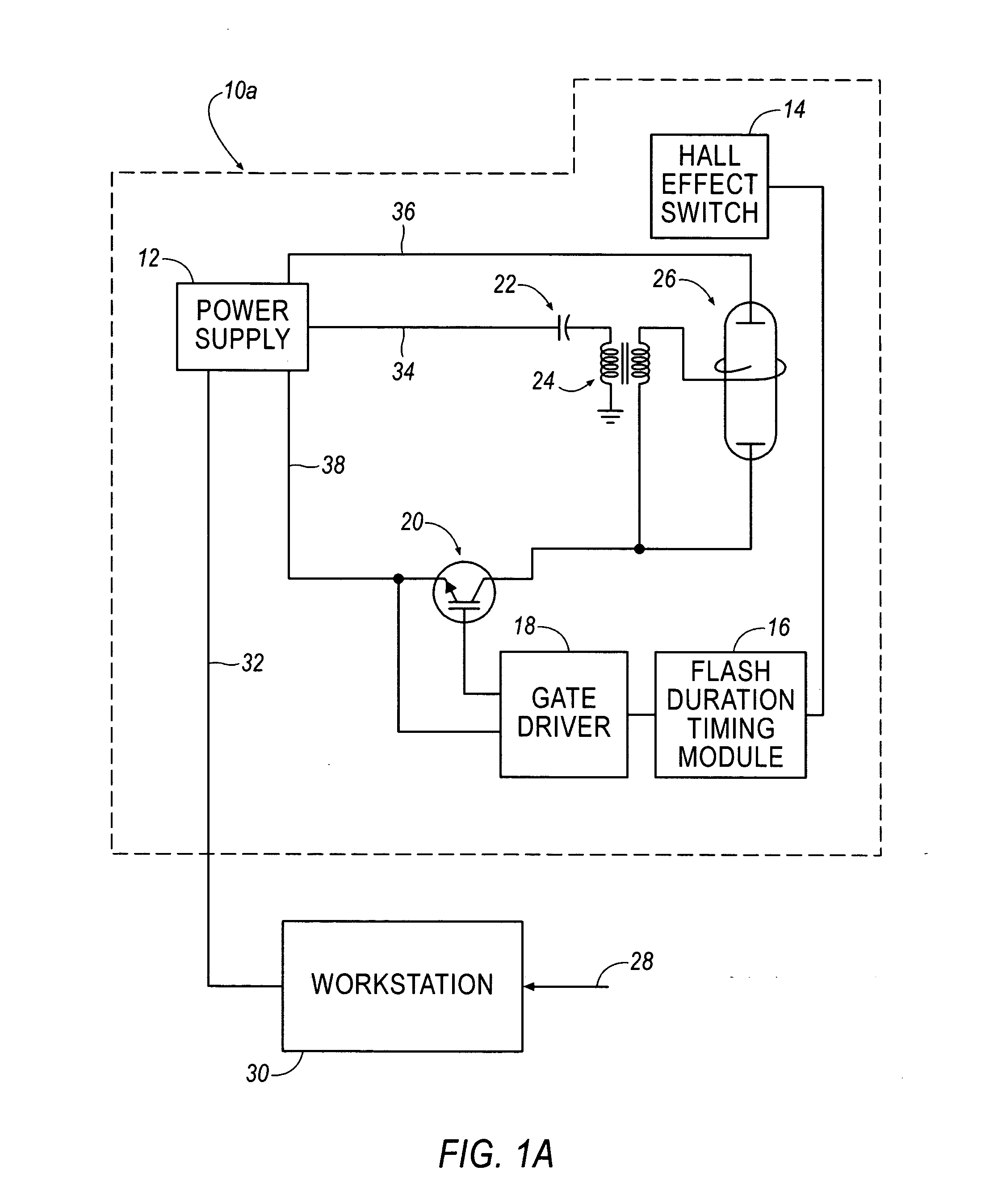
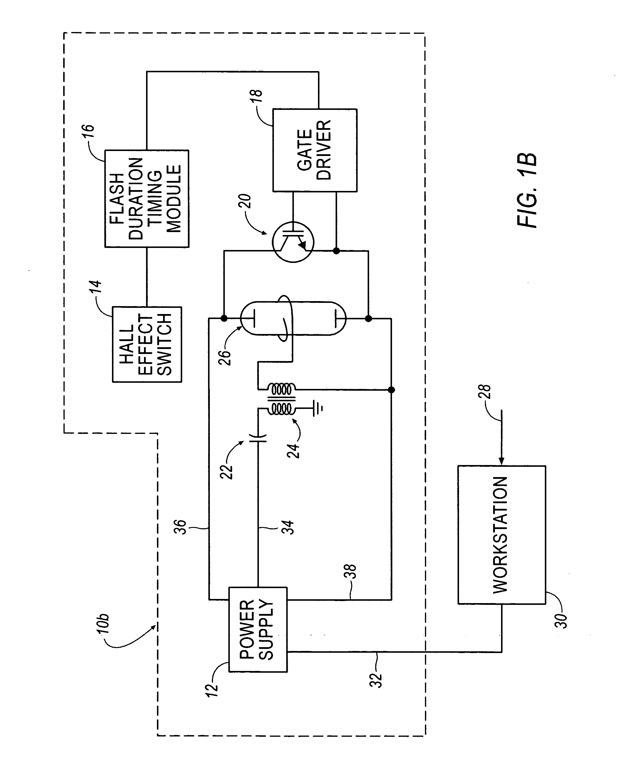
[0036] Referring to FIGS. 1A and 1B, an add-on pulse controller device is shown generally at 10a and 10b, respectively. As illustrated, the pulse controller device 10a is arranged in a series configuration, and the pulse controller device 10b is arranged in a parallel configuration. Each pulse controller device 10a, 10b is arranged to include a power supply 12, a Hall effect switch 14, a flash duration timing module 16, a gate driver 18, an Insulated Gate Bipolar Transistor (IGBT) 20, a power supply capacitor 22, a trigger transformer 24, and a flashtube 26.

[0037] As illustrated, a video synchronize signal 28 is fed into a workstation 30, such as a personal computer, that drives the power supply 12. In operation, when the workstation 30 issues a control signal over path 32 to the power supply 12, the power supply 12 issues a trigger pulse output signal (e.g. a 250 volt capacitive discharge pulse) over path 34 to the power supply capacitor bank 22, which excites the trigger transfor...


PUM

PropertyMeasurementUnit
time durationaaaaaaaaaa
electrical poweraaaaaaaaaa

Abstract

A pulse controller device for controlling the excitation of a heat source used in thermographic imaging is disclosed. The pulse controller device comprises a power supply, a heat source coupled to the power supply, a device coupled to the power supply signaling the power supply to deliver electrical power to the heat source, a sensor for sensing the delivery of electrical power to the heat source, a flash duration module coupled to said sensor for measuring a duration of time, and a gate device coupled to said flash duration module for gating the electrical power utilized by the heat source. A method for thermographically evaluating a sample is also disclosed. It is emphasized that this abstract is provided to comply with the rules requiring an abstract that will allow a searcher or other reader to quickly ascertain the subject matter of the technical disclosure. It is submitted with the understanding that it will not be used to interpret or limit the scope or meaning of the claims.

Description

RELATED APPLICATION INFORMATION [0001] The present invention is related to provisional patent application Ser. Nos. 60 / 490,674 and 60 / 490,880, both filed on Jul. 29, 2003.BACKGROUND OF THE INVENTION [0002] 1. Field of the Invention [0003] The present invention generally relates to thermographic imaging and more particularly relates to pulsed thermography. [0004] 2. Description of the Related Art [0005] Active thermography is used to nondestructively evaluate (NDE) samples for sub-surface defects. It is effective for uncovering internal bond discontinuities, delaminations, voids, inclusions, and other structural defects that are not detectable by visual inspection of the sample. Generally, active thermography involves heating or cooling the sample to create a difference between the sample temperature and the ambient temperature and then observing the infrared thermal signature that emanates from the sample as its temperature returns to ambient temperature. In application, pulsed ther...

Claims


Application Information

Patent Timeline
Patent Type & Authority Applications(United States)
IPC IPC(8): G01N25/72
CPCG01N25/72
Inventor SHEPARD, STEVEN M.YOUNG, TIMOTHY
Owner THERMAL WAVE IMAGING
Why Eureka
Try Eureka