Ultra-broadband UV microscope imaging system with wide range zoom capability

a microscope imaging and wide-range zoom technology, applied in the field of ultra-broadband ultraviolet (uv) catadioptric imaging microscope systems, can solve the problems of limiting aberration in these systems, unable to provide complete correction of residual (secondary and higher order) lateral color over a broad uv spectrum, and limiting aberration in the system, so as to achieve high numerical aperture and high performance.

Inactive Publication Date: 2005-03-17
KLA TENCOR TECH CORP
View PDF12 Cites 9 Cited by
  • Summary
  • Abstract
  • Description
  • Claims
  • Application Information

AI Technical Summary

Benefits of technology

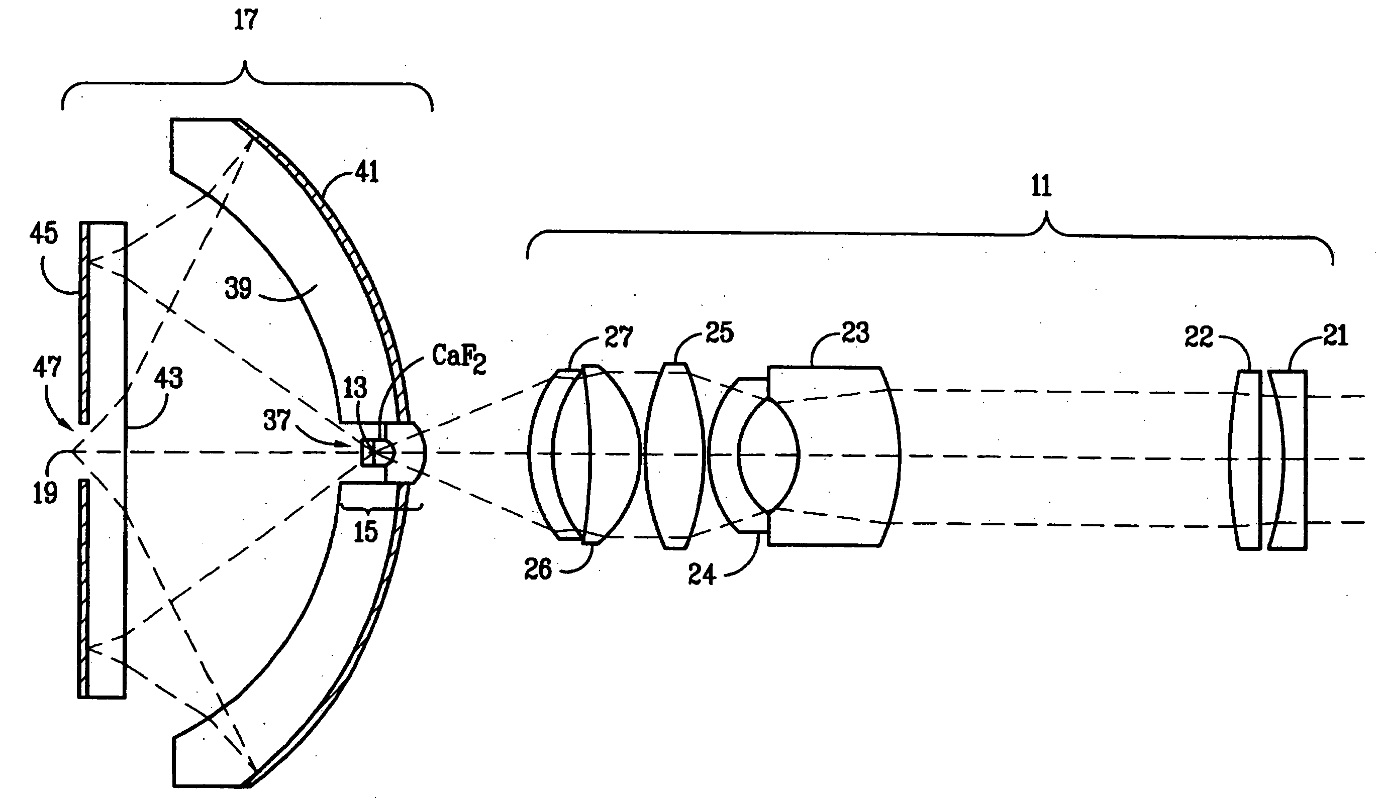
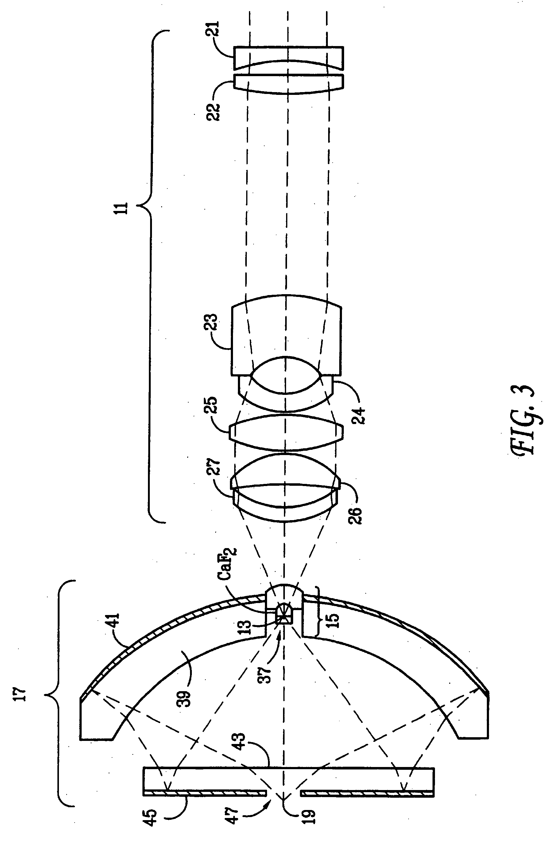
[0013] The invention is a high performance, high numerical aperture, ultra-broad spectral region catadioptric optical system with zooming capability, comprising an all-refractive zooming tube lens section with one collimated conjugate, constructed so that during zooming its higher-order chromatic aberrations (particularly higher-order lateral color) do not change; and a hon-zooming high numerical aperture catadioptric objective section which compensates for the uncorrected (but stationary during zoom) higher-order chromatic aberration residuals of the zooming tube lens section.

Problems solved by technology

This is the limiting aberration in these systems when a broad spectral range is covered.
The system also incidentally corrects for narrow band lateral color, but fails to provide complete corrections of residual (secondary and higher order) lateral color over a broad UV spectrum.
This is the limiting aberration in the system when a broad spectral range is covered.
In the deep UV, there are very few materials that can be used for chromatic aberration correction, making the design of high performance, broadband optics difficult.
It is even more difficult to correct for chromatic aberrations for ultra-broadband optics with wide-range zoom.

Method used


Image

  • Ultra-broadband UV microscope imaging system with wide range zoom capability
  • Ultra-broadband UV microscope imaging system with wide range zoom capability
  • Ultra-broadband UV microscope imaging system with wide range zoom capability

Examples


first embodiment

[0044] zoom lenses provides linear zoom motion with a fixed detector array position. FIG. 5 shows the 36.times. zoom arrangement of the lenses, the 64.times. zoom arrangement of the lenses and the 100.times. zoom arrangement of the lenses. The detector array 140 (not shown) is fixed. The zooming tube lens design. 141 is comprised of two moving lens groups 142 and 143. The beam splitter is not shown in this and later figures for the purpose of clarity. The following table lists the surfaces shown in FIG. 5, where the surface numbering begins at “0” for the final image counting towards the object being inspected.

[0045] Lens Data for the First Embodiment 0.90 N.A., fixed detector, 36.times.-100.times. zoom, 1.0 mm field size

SurfaceRadiusThicknessGlass0—30.000000 36XAir152.396279 64X318.839746100X1−46.8434424.000000Calciumfluoride267.0173790.999804Air3122.0034947.000000Silica4−34.9441444.496612Air5−42.8838894.000000Calciumfluoride6−1.5857e+03339.659737 36XAir298.114540 64X279.99739210...

second embodiment

[0046] zoom lenses provides linear zoom motion with a moving detector array position and FIG. 6 shows the 36.times. zoom arrangement of the lenses, the 64.times. zoom arrangement of the lenses and the 100.times. zoom arrangement of the lenses. The following table lists the surfaces shown in FIG. 6, where the surface numbering begins at “0” for the final image incrementing by 1 towards the object being inspected.

[0047] Lens Data for the Second Embodiment 0.90 N.A., moving detector, 36.times. to 100.times. zoom, 1.0 mm field size

SURFACERADIUSTHICKNESSGLASS0Infinity110.004950 36XAir405.371660 64X785.131189100X173.1566215.000000Calciumfluoride2−609.63843718.230155Air3−30.3030903.500000Calciumfluoride444.3616564.000000Air5−51.3189997.765282Silica6−23.2311951.564401Air7−119.7563154.000000Calciumfluoride840.00270112.019418Air954.59478910.000000Calciumfluoride10−28.9237440.100000Air11−29.9574115.000000Silica12−156.281481202.434836 36XAir108.230318 64X64.650627100X13188.6647704.500000Silic...


PUM

PropertyMeasurementUnit
wavelengthaaaaaaaaaa
thicknessaaaaaaaaaa
wavelengthaaaaaaaaaa

Abstract

An ultra-broadband ultraviolet (UV) catadioptric imaging microscope system with wide-range zoom capability. The microscope system, which comprises a catadioptric lens group and a zooming tube lens group, has high optical resolution in the deep UV wavelengths, continuously adjustable magnification, and a high numerical aperture. The system integrates microscope modules such as objectives, tube lenses and zoom optics to reduce the number of components, and to simplify the system manufacturing process. The preferred embodiment offers excellent image quality across a very broad deep ultraviolet spectral range, combined with an all-refractive zooming tube lens. The zooming tube lens is modified to compensate for higher-order chromatic aberrations that would normally limit performance.

Description

[0001] This application is a continuation in part of co-pending U.S. patent application Ser. No. 09 / 046,814, entitled “High NA System for Multiple Mode Imaging,” filed on Mar. 24, 1998, which is a continuation in part of U.S. Pat. No. 5,999,310, entitled “Ultra-Broadband UV Microscope Imaging System with Wide Range Zoom Capability,” filed on Aug. 7, 1997, which is a continuation in part of U.S. patent application Ser. No. 08 / 681,528, entitled “Broad Spectrum Ultraviolet Catadioptric Imaging System,” filed on Jul. 22, 1996, all of which are hereby incorporated by reference.BACKGROUND OF THE INVENTION [0002] 1. Field of the Invention [0003] This invention relates generally to an ultra-broadband ultraviolet (UV) catadioptric imaging microscope system, and more specifically to an imaging system that comprises a UV catadioptric objective lens group and a wide-range zooming tube lens group. [0004] 2. Description of the Related Art [0005] Catadioptric imaging systems for the deep ultraviol...

Claims


Application Information

Patent Timeline
Patent Type & Authority Applications(United States)
IPC IPC(8): G01N21/33G02B13/14G02B17/02G02B17/08G02B21/16G03C5/16G03F1/84G03F3/00G03F7/20H04N5/225
CPCG02B17/023G02B17/0808G02B17/0812G02B17/0856G02B17/086G02B17/0892G03F7/7065G02B21/16G03F1/84G03F7/70225G03F7/70275G03F7/70616G02B17/0896
Inventor SHAFER, DAVID R.CHUANG, YUNG-HOTSAI, BIN-MING B.
Owner KLA TENCOR TECH CORP
Why Eureka
Try Eureka