Polymer stent

a polymer and stent technology, applied in the field of stents, can solve the problems of unsuitability of polyurethanes and benign vessels of polymer coatings exposed, and achieve the effect of superior performance in the body

Inactive Publication Date: 2005-03-17
ADVANCED BIO SURFACE
View PDF5 Cites 38 Cited by
  • Summary
  • Abstract
  • Description
  • Claims
  • Application Information

AI Technical Summary

Benefits of technology

[0007] The present application discloses a polymer stent as well as a polymer coated stent. Both the polymer formulation and a processing methodology are disclosed. The polyurethane described

Problems solved by technology

Although these drug-eluting stents have been shown to be both safe and effective, once the drug is delivered or “fully gone” the polymer coating that is exposed may not be beni

Method used


Image

  • Polymer stent
  • Polymer stent
  • Polymer stent

Examples


Embodiment Construction

[0019] Stent Construction

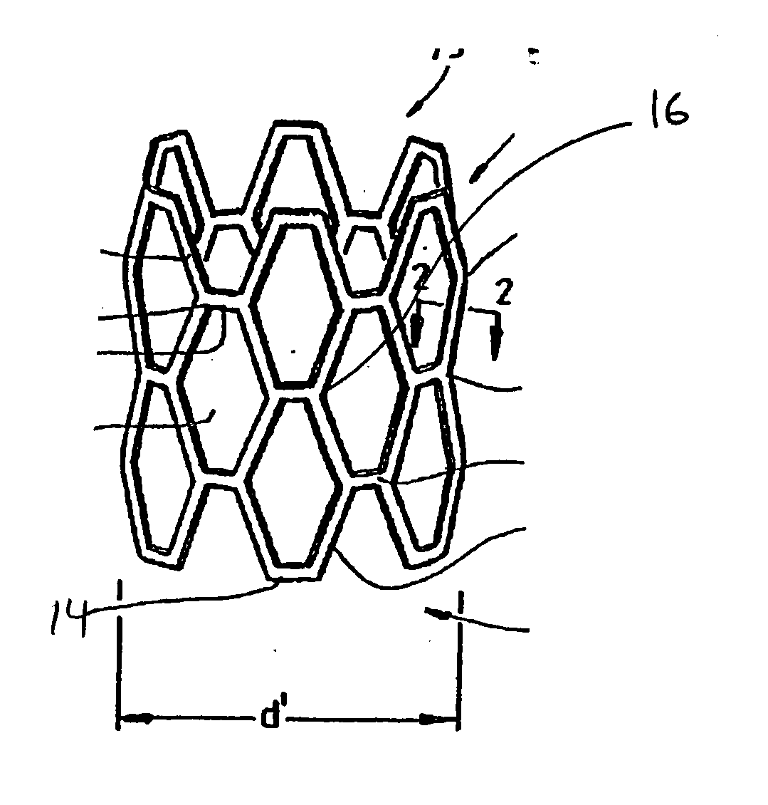
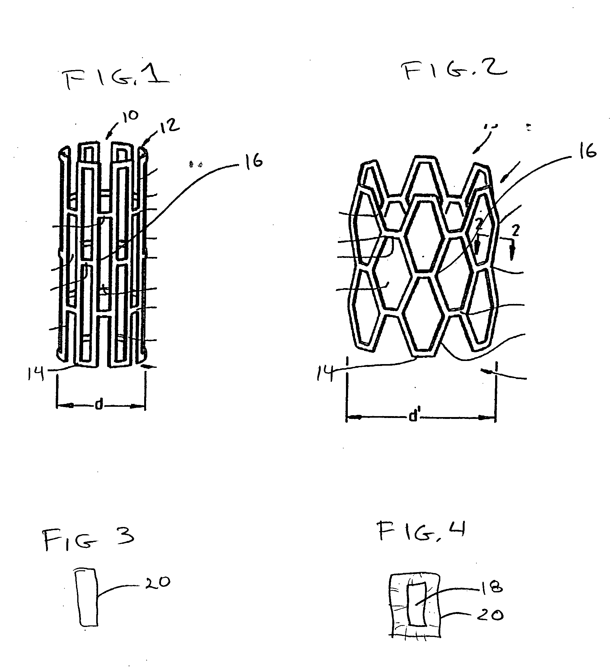
[0020]FIG. 1 shows an interluminal stent 10 of the well known “Palmaz” type. In general stents of this type are made from a lattice or mesh form body 12 made from metal. Nitinol and stainless steel are both used for stents of this type. Typically the stent is laser cut and then coated with a polymer for controlled elution of a drug. The drug loaded stent is then crimped onto a balloon delivery system with an overall diameter of “d” and sterilized. During delivery, the stent 10 is expanded into a delivered state seen in FIG. 2. In this condition the stent is expanded to a diameter “d”. Some portions of the stent remain fairly invariant in length such as strut element 14, however other elements such as strut 16 are plastically deformed. The strut structures form a series of interlaced apertures. It is expected that the entire stent will be coated with the polymer and that mechanical properties of the polymer will accommodate flexure and plastic deformation wi...


PUM


Abstract

A polymer intravascular stent that is resorable over a period of time containing a drug, which is delivered to the vascular wall during the absorption of the polymer material. A gradient of drug concentration may be established in the polymer.

Description

CROSS REFERENCE [0001] The present case is the utility application based upon US Provisional Application 60 / 472,125 filed May 21, 2003 entitled “Drug Eluting Polyurethane Stent” which is incorporated by reference herein in its entirety.FIELD OF THE INVENTION [0002] The present invention relates generally to a medical device, and more particularly to a stent with a polymer coating or polymer structure containing a drug to. prevent restenosis. BACKGROUND OF THE INVENTION [0003] Stents are widely used for treating coronary vessel disease as well as for propping open other lumens within the body. The earliest form of stent construction involved a “bare metal” wire mesh structure. Later some versions of the device were made from a material exhibiting a “shape memory” attribute. Devices of this type can “self deploy”. Other versions of the device were deployed through the use of a balloon expansion device that expanded the stent into contact with the wall of the vessel or lumen. [0004] Ba...

Claims


Application Information

Patent Timeline
IPC IPC(8): A61F2/00A61F2/06A61F2/90
CPCA61F2/91A61F2/915A61F2230/0013A61F2250/0067A61F2002/91541
Inventor FELT, JEFFREY C.ARSENYEN, ALEXANDERRYDELL, MARK A.
Owner ADVANCED BIO SURFACE
Why Eureka
Try Eureka