
Electric machine with a damping device

a technology of damping device and electric machine, which is applied in the direction of dynamo-electric converter control, motor/generator/converter stopper, and magnetic circuit shape/form/construction, etc., can solve the undesirable voltage peaks due to switching operations, diminish and reduce the useful life of insulation. , to achieve the effect of large damping, large internal magnetic reversal loss, and large damping

Inactive Publication Date: 2005-03-24
SIEMENS AG
View PDF10 Cites 16 Cited by
  • Summary
  • Abstract
  • Description
  • Claims
  • Application Information

AI Technical Summary

Benefits of technology

[0026] According to an advantageous embodiment of the electric machine, no additional components are required and instead, already existing openings in the laminated core can be used as core for the damping inductance. This saves costs and installation space. In motors with forced cooling, the heat dissipated in the damping inductance is well coupled to the heat carried away from the motor by the sheet metal of the motor. Accordingly, the damping inductance can sustain a large power density without additional measures, which also reduces the required installation space.
[0044] A particularly large damping effect can be achieved by tapping the magnetic flux of the damping inductance with a secondary winding associated with the damping inductance and dissipating the current in the secondary winding in a resistor.

Problems solved by technology

During operation of electric motors powered by pulse converters, the switching operations of the converter can cause voltage peaks between the motor winding and the grounded motor body.
If the switching operations on the input terminals are periodic and their fundamental frequency or harmonics are close to the characteristic frequencies of the reactant network conductor of the motor winding, then the voltage peaks can become so large as to diminish the useful life of the insulation.
Voltage peaks due to switching operations are therefore undesirable.
Similar problems can occur with electric machines suffering from transient overvoltages.
Nevertheless, there remain problems of breakdowns in the star point of a synchronous motor produced with exciter coil technique.
A drawback of conventional devices is the need for additional installation space and added costs.

Method used


Image

  • Electric machine with a damping device
  • Electric machine with a damping device
  • Electric machine with a damping device

Examples


Embodiment Construction

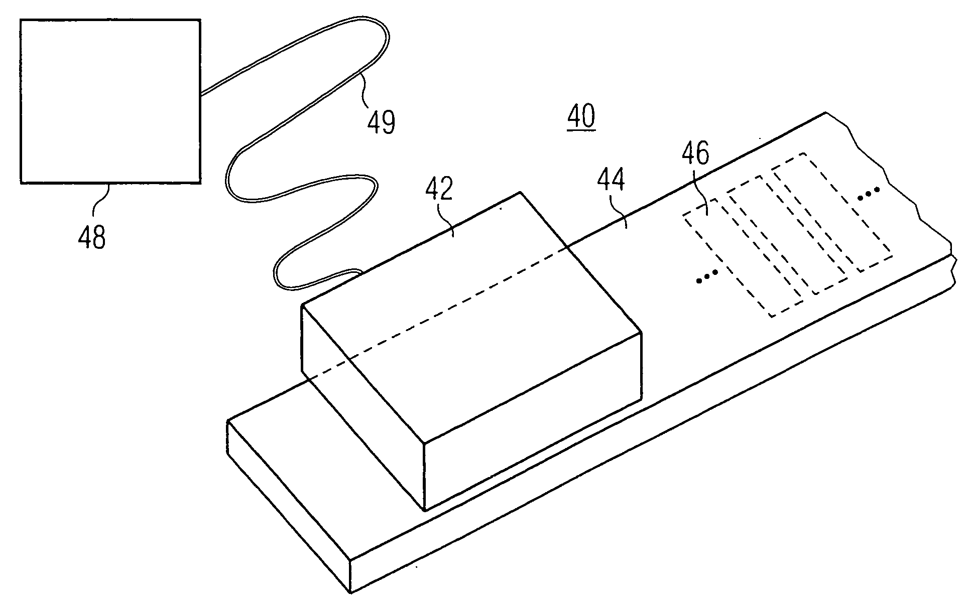
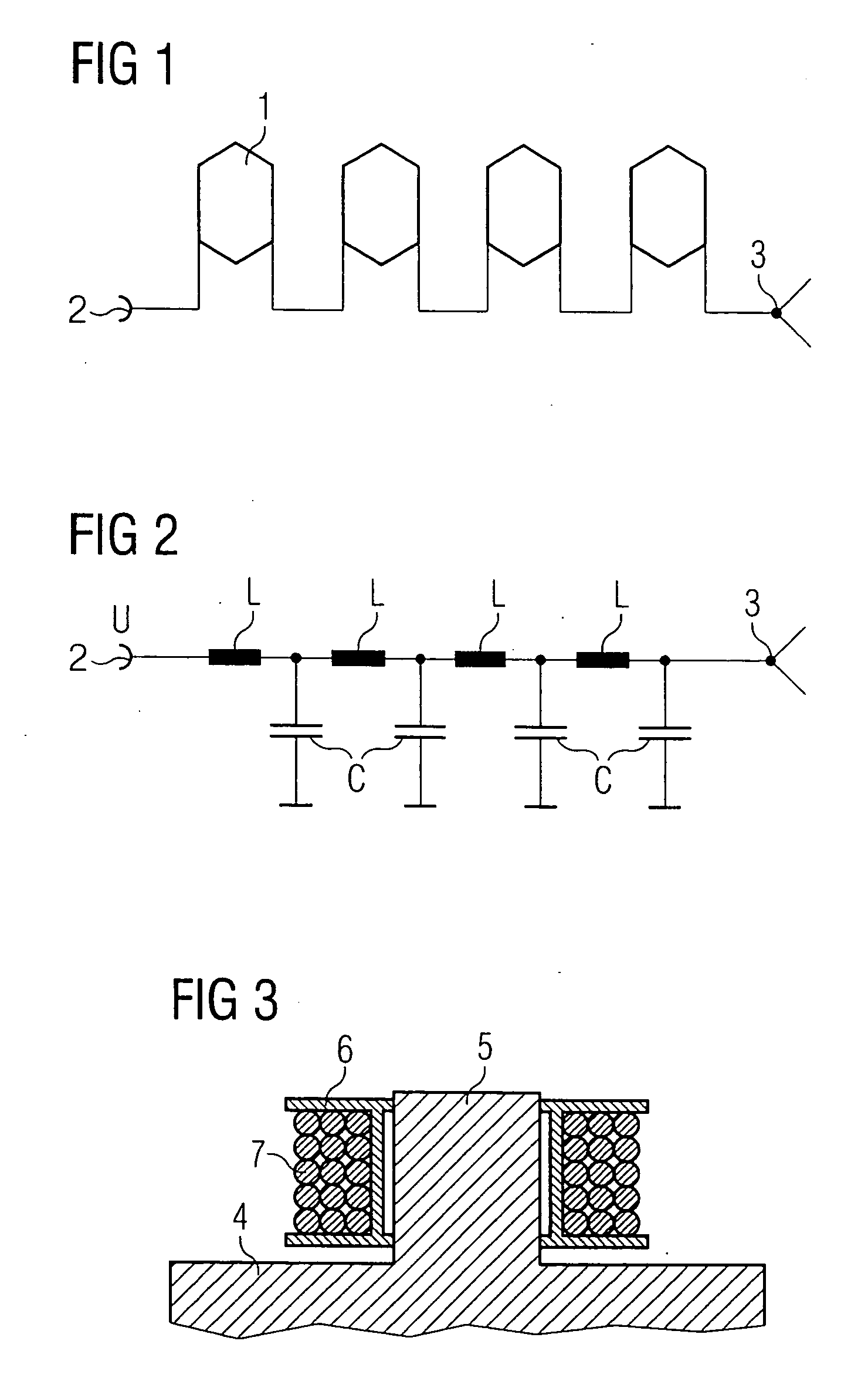
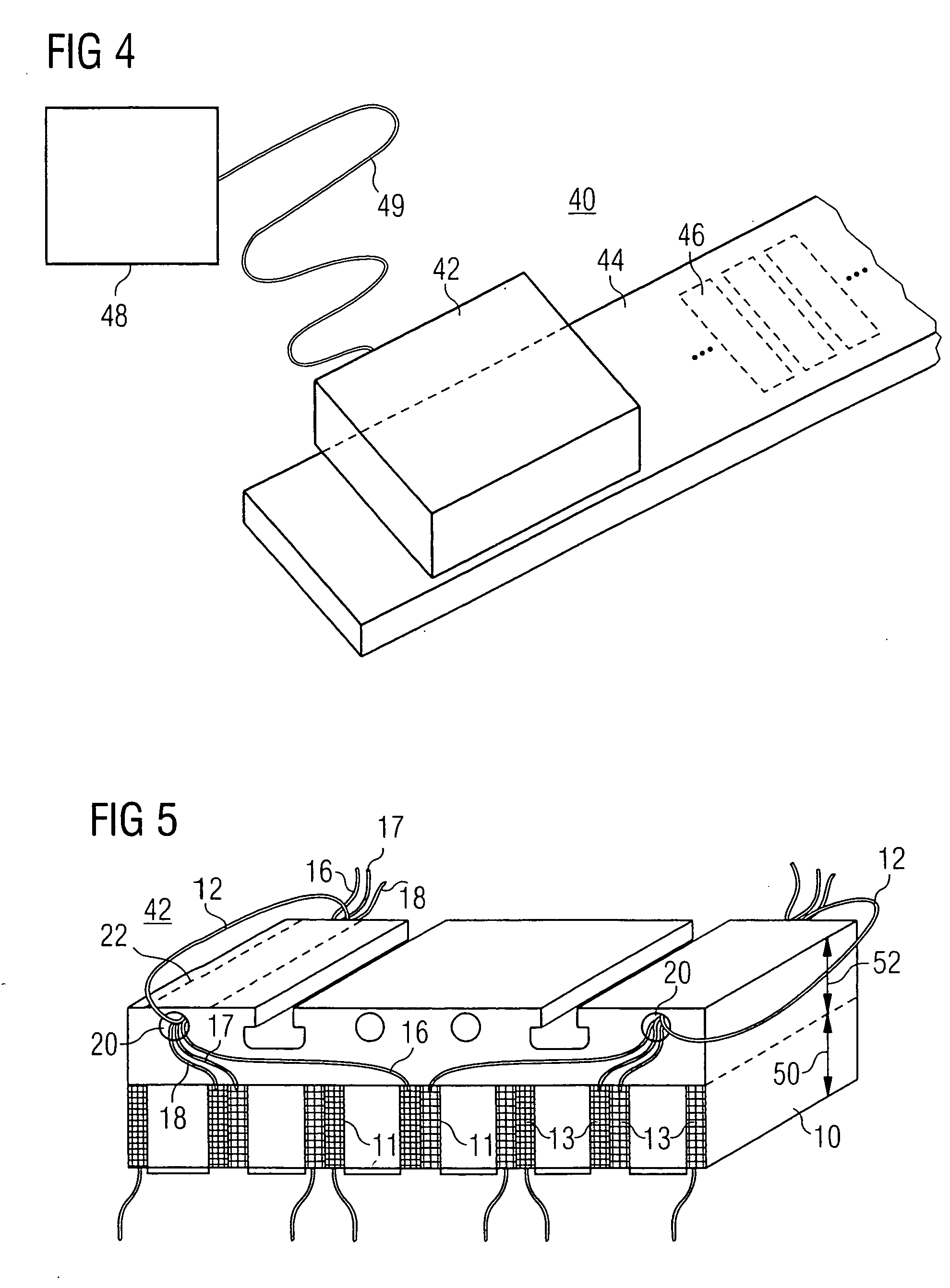
[0065] Throughout all the Figures, same or corresponding elements are generally indicated by same reference numerals. These depicted embodiments are to be understood as illustrative of the invention and not as limiting in any way. It should also be understood that the drawings are not necessarily to scale and that the embodiments are sometimes illustrated by graphic symbols, phantom lines, diagrammatic representations and fragmentary views. In certain instances, details which are not necessary for an understanding of the present invention or which render other details difficult to perceive may have been omitted.

[0066] Turning now to the drawing, and in particular to FIG. 1, there is shown a schematic circuit diagram of a typical winding strand of a three-phase machine, wherein four coils 1 are implemented in exciter coil technique. The exciter coils 1 depicted an hexagons are connected in series and electrical power is supplied via an input terminal 2. The end of the winding strand...


PUM


Abstract

An electric AC machine with a primary section and a secondary section is disclosed. The primary section has a region facing the secondary section and a region facing away from the secondary section. The region facing the secondary section has windings adapted to receive an AC current. The winding of the primary section has at least one phase conductor which at least partially extends in or on the region of the primary section facing away from the secondary section, thereby producing a magnetic field that extends outside the secondary section. This arrangement can reduce overvoltages and eliminate voltage breakdowns at the star point of winding strands of a synchronous motor.

Description

CROSS-REFERENCES TO RELATED APPLICATIONS [0001] This application claims the priority of German Patent Application, Serial No. 103 43 293.0, filed Sep. 18, 2003, pursuant to 35 U.S.C. 119(a)-(d), the disclosure of which is incorporated herein by reference. BACKGROUND OF THE INVENTION [0002] The present invention relates to an electric machine with a damping device. The electric machine is an AC machine or a three-phase machine, and can be implemented as a rotary machine or as a linear motor. [0003] Nothing in the following discussion of the state of the art is to be construed as an admission of prior art. [0004] Electric machines, in particular synchronous motors, are frequently constructed by inserting specially formed winding wires in rotor or stator grooves. The winding wires are connected at the winding head to form winding strands. A winding strand can have several coils, depending on the number of poles. In three-phase machines, each phase has at least one winding strands, with...

Claims


Application Information

Patent Timeline
IPC IPC(8): H02K3/16H02K3/20H02K41/02
CPCH02K3/16H02K1/146H02K41/031H02K3/20
Inventor HOPPE, THOMASSTOIBER, DIETMAR
Owner SIEMENS AG
Learn More