
Concealed antenna

a technology of antennas and antenna beams, applied in the direction of protective material radiating elements, instruments, portable computers, etc., can solve the problems of direct reduction of communication quality, large effect of manufacturing and fabricating the antenna system, and reduced antenna radiation angles, so as to increase the reliability of the antenna, reduce the cost of manufacturing and fabricating the antenna system, and reduce transmission loss

Active Publication Date: 2005-03-24
QUANTA COMPUTER INC
View PDF7 Cites 39 Cited by
  • Summary
  • Abstract
  • Description
  • Claims
  • Application Information

AI Technical Summary

Benefits of technology

[0010] It is therefore an object of the invention to provide a concealed antenna. The antenna is directly configured in the remained space of regions on the base module for holding hinges of the LCD, without using the conventional RF coaxial cable to transmit RF signals to the wireless module. Therefore, the cost of manufacturing and fabricating the antenna system can be lowered, and the transmission loss can be reduced, thereby increasing the antenna reliability.
[0011] The invention achieves the above-identified objects by providing a concealed antenna applied in a notebook computer. The notebook computer includes a display module having hinges, and a base module. The base module includes regions for inserting the hinges, a motherboard having a positive region and a negative region, a transmission line, and a wireless module. The concealed antenna includes a feed-in end for electrically coupling with the positive region, and a ground end for electrically coupling with the negative region. The concealed antenna, configured in the region for inserting the hinge and installed on the motherboard, sends out signals to the wireless module via the transmission line. Therefore, the conventional RF coaxial cable is not needed, and thus the cost of manufacturing and fabricating the antenna system can be reduced.
[0012] The invention achieves the above-identified objects by providing a notebook computer including a display module and a base module. The display module has hinges, and the base module has regions for inserting the hinges so that the display module can be opened and closed relative to the base module via the hinges. The base module includes a motherboard and an antenna, such as a surface mounting device (SMD) typed antenna. The motherboard has a positive hole and a negative hole, located under the region for inserting the hinge. The antenna is configured in the region for inserting the hinge and installed on the motherboard. The antenna includes a feed-in end for inserting into the positive hole, and a ground end for inserting into the negative hole. The base module further includes a transmission line for electrically connecting the antenna and the wireless module. The antenna, configured in the region for inserting the hinge, has good compatibility with the original mechanism of the notebook computer, and shortens significantly its distance from the wireless module, so the transmission loss can be reduced and the system reliability can be enhanced.

Problems solved by technology

Furthermore, how the antenna is configured in the system will have a great effect on the cost of manufacturing the whole system.
As a result, antenna radiation angles will be reduced and dead space in communication will be increased, which directly reduces communication quality.
Moreover, as the wireless system is fabricated, additional devices, such as hooks for fixing the RF coaxial cable and fixing pieces for fixing the shielding aluminum foil, are required to fix the RF coaxial cable, which further increases the cost.
The labor hours for configuring and positioning the RF coaxial cable will largely increase the fabrication cost.

Method used


Image

  • Concealed antenna
  • Concealed antenna
  • Concealed antenna

Examples


Embodiment Construction

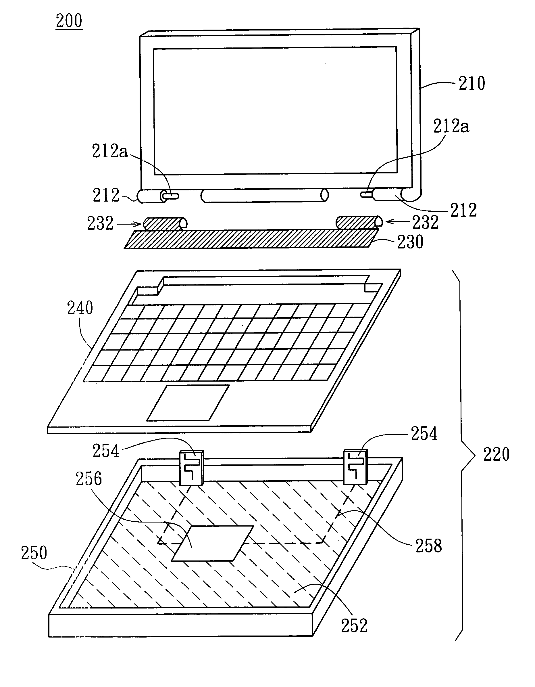
[0022] The main feature of the concealed antenna in the invention is that the antenna is configured in the region on the base module for inserting the hinge of the LCD module. The motherboard is provided for fixing the antenna and connecting the feed-in point of the antenna. High-frequency energy transmission between the feed-in point of the antenna and the wireless module can be directly carried out via a stripline or a microstrip-line disposed on the motherboard without using the conventional RF coaxial cable. Therefore, the cost of manufacturing the antenna system and fabricating the notebook computer can be reduced significantly.

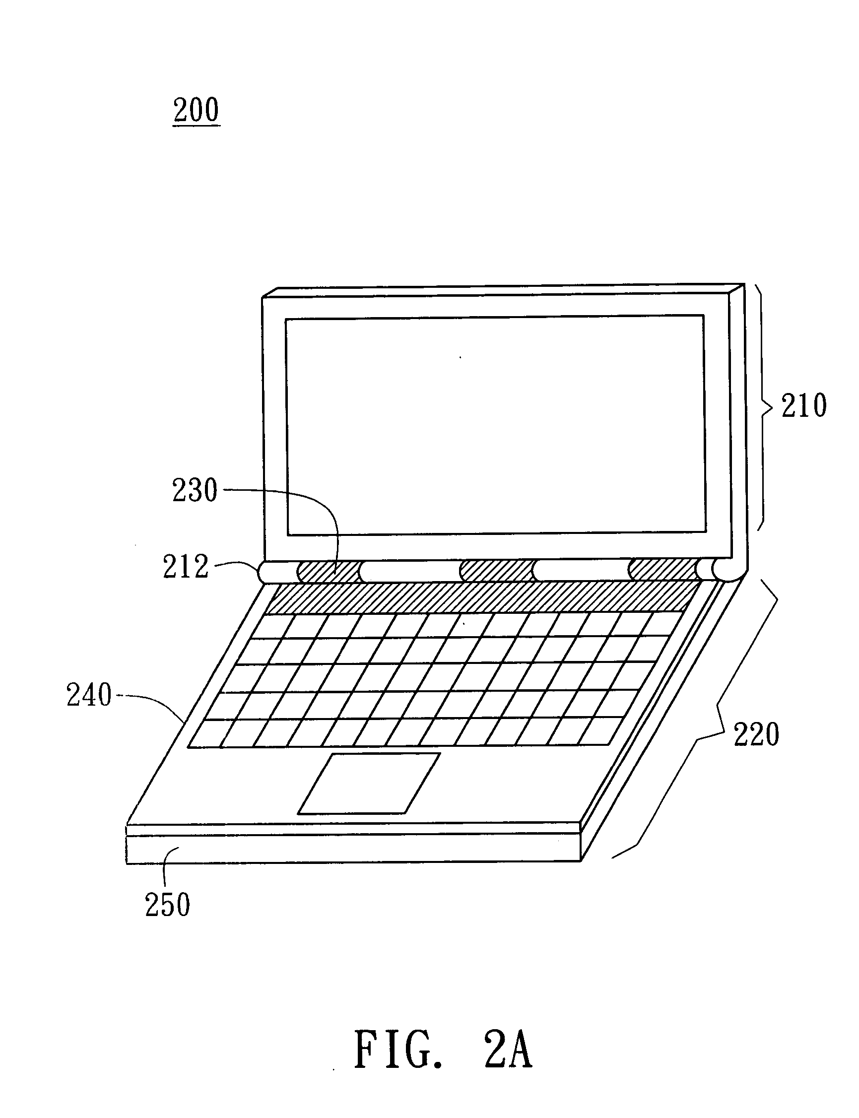
[0023] Referring to FIG. 2A and FIG. 2B, a perspective view and an exploded view of a notebook computer having a concealed antenna according to a preferred embodiment of the invention are shown. The notebook computer 200 includes a LCD module 210 and a base module 220. The LCD module 210 has hinge parts 212, and the base module 220 includes a hinge cove...


PUM


Abstract

A concealed antenna is applied to a notebook computer. The notebook computer includes a displaying module and a base module. The displaying module has a hinge, and the base module includes a region for inserting the hinge, a motherboard, a transmission line, and a wireless module. The motherboard includes a positive region and a negative region. The concealed antenna includes a feed-in end and a ground end for respectively electrically coupling with the positive region and the negative region. The concealed antenna, configured in the region for inserting the hinge and installed on the motherboard, transmits antenna signals to the wireless module via the transmission line.

Description

[0001] This application claims the benefit of Taiwan application Serial No. 92126037, filed Sep. 19, 2003, the subject matter of which is incorporated herein by reference. BACKGROUND OF THE INVENTION [0002] 1. Field of the Invention [0003] The invention relates in general to a concealed antenna, and more particularly to a concealed antenna mounted directly on the motherboard of a notebook computer. [0004] 2. Description of the Related Art [0005] In a wireless communication system, such as a notebook computer or a mobile phone, an antenna is a device for transmitting and receiving electromagnetic waves. The way that an antenna is designed and the location that it is mounted in the system influences its radiation field pattern, and the quality of signal transmission. Furthermore, how the antenna is configured in the system will have a great effect on the cost of manufacturing the whole system. [0006] Referring to FIG. 1, a schematic view of a conventional notebook computer equipped wi...

Claims


Application Information

Patent Timeline
IPC IPC(8): H01Q1/08H01Q1/22H01Q1/38H01Q1/40H01Q21/28
CPCG06F1/1616G06F1/1698H01Q1/084H01Q21/28H01Q1/2266H01Q1/38H01Q1/40H01Q1/22
Inventor LIN, HUEI
Owner QUANTA COMPUTER INC
Learn More