Active agent delivery systems including a miscible polymer blend, medical devices, and methods

a technology of active agents and polymers, applied in the field of active agent delivery systems including miscible polymer blends, medical devices, and methods, can solve the problems of limited active agent range, structural failure, limitations of conventional active agent delivery systems, etc., and achieve the effects of not preventing permeation, increasing lag time, and slowing the rate of permeation

Inactive Publication Date: 2005-03-24
MEDTRONIC INC
View PDF70 Cites 80 Cited by
  • Summary
  • Abstract
  • Description
  • Claims
  • Application Information

AI Technical Summary

Benefits of technology

The term barrier layer refers to a polymer layer that controls the rate of release of the active agent(s). It does not prevent permeation; r...

Problems solved by technology

Conventional active agent delivery systems suffer from limitations that include structural failure due to cracking and delamination from the device surface.
Furthermore, they tend to be limited in terms of the...

Method used


Image

  • Active agent delivery systems including a miscible polymer blend, medical devices, and methods
  • Active agent delivery systems including a miscible polymer blend, medical devices, and methods
  • Active agent delivery systems including a miscible polymer blend, medical devices, and methods

Examples


example 1

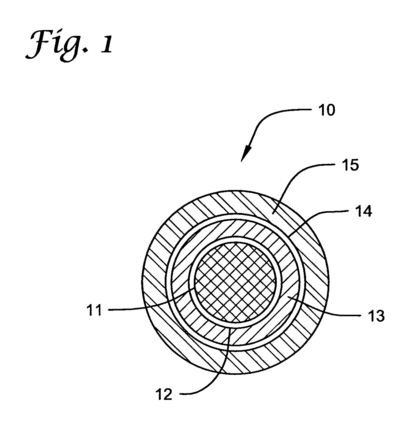
Stainless steel coronary S7 stents (manufactured by Medtronic AVE) were ultrasonically cleaned with isopropanol (IPA) for 30 minutes and allowed to dry thoroughly. The stents were then sprayed with a 0.25% solution of TECOPLAST (TP) polyurethane (Thermedics Polymer) in THF as an initial primer. The stents were then heat-treated at 215-220° C. for 5-15 minutes to create better adhesion between metal and polymer interface. Next, each stent was sprayed with 1% solution of mycophenolic acid (Sigma-Aldrich) in TECOPLAST polyurethane (25 wt-% loading of active agent) using tetrahydrofuran (THF) as solvent. This represents the inner layer with a target coating of 400 micrograms (μg) + / −10% and a thickness of approximately 4 micrometers (μm). The stent was then vacuum-dried at 45° C. overnight and then weighed. After weighing, a thin coating of TECOPLAST polyurethane (1% solution in THF) was sprayed over the first or inner layer to form a barrier. This barrier formed the middle layer that ...

example 2

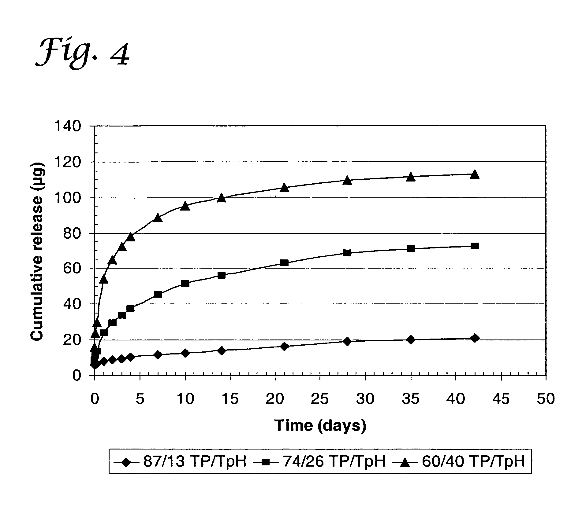
Using the same procedure as in Example 1, similar dual active agent-coated stents were fabricated except in this case the blend of the outer layer of TECOPLAST / PEVA was replaced with TECOPLAST / TECOPHILIC polyurethanes (Thermedics Polymer). The release of sulfasalazine from a blend of TECOPLAST (TP) and TECOPHILIC (TpH) polyurethanes for use as an outer layer is shown in FIG. 4. The release rate of sulfasalazine increased as the percentage of TECOPHILIC polyurethane in the blend increased.

example 3

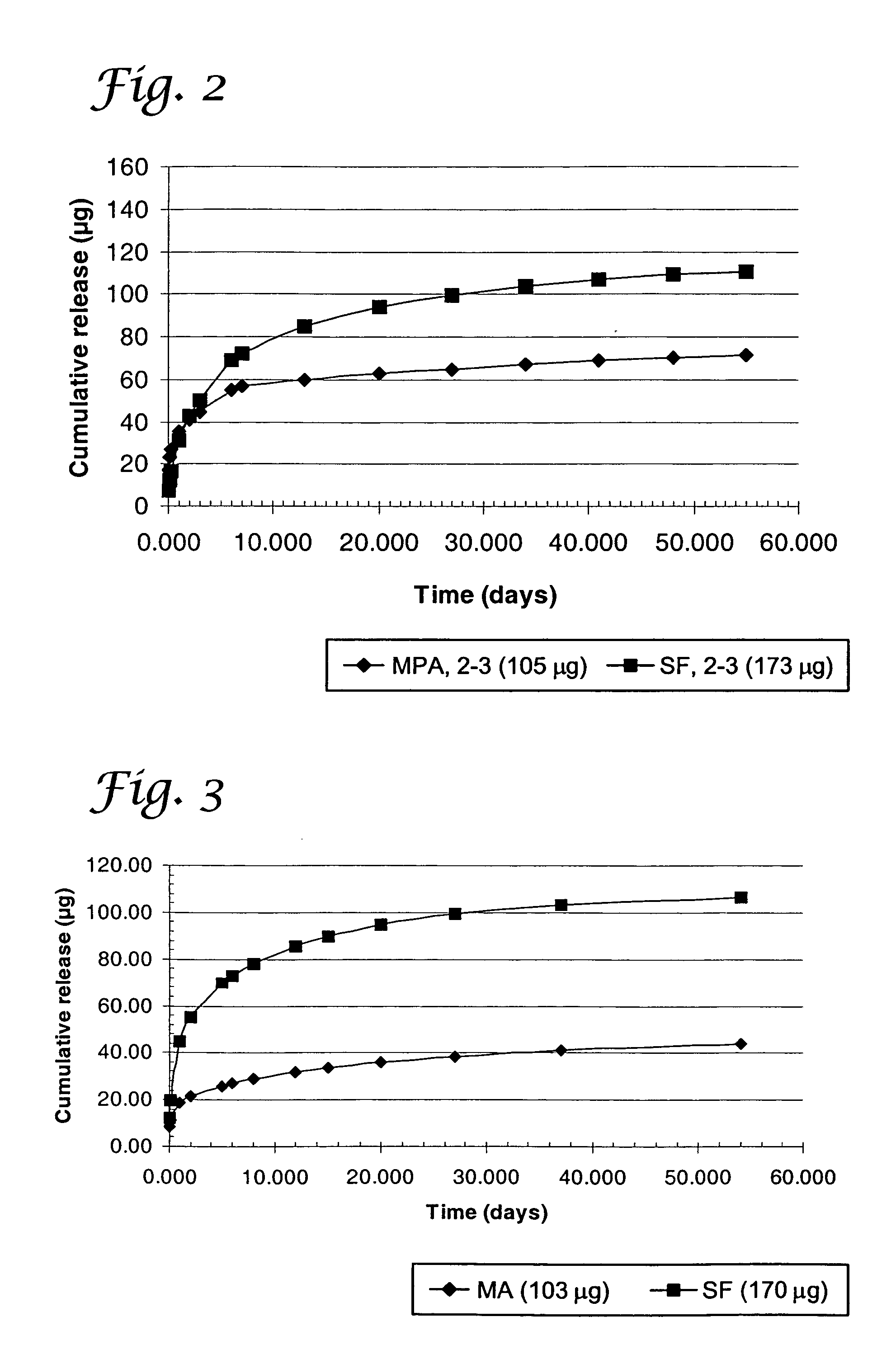
Coated stents were fabricated as described in Example 1 and FIG. 1, except the design consisted of no middle barrier and its inner layer consisted of a blend of 80% TECOPLAST / 20% TECOTHANE 75D or just TECOPLAST alone, and the outer layer consisted of a blend of 70% TECOPLAST / 20% TECOTHANE 75D. This shows that polymer blends can be used to change the release characteristics of active agents. The release characteristics of this system are shown in FIG. 5. In FIG. 5, MA1-2 is the average cumulative release of mycophenolic acid from samples 1 and 2; SF1-2 is the average cumulative release of sulfasalazine from samples 1 and 2. For samples 1 and 2, the inner layer contains 30% of mycophenolic acid in TECOPLAST polyurethane and the outer layer contains 35% of sulfasalazine in a blend of 70% TECOPLAST and 30% of TECOTHANE 75D polyurethanes. Similarly, MA3-4 is the average cumulative release of mycophenolic acid from samples 3 and 4 and SF3-4 is the average cumulative release of sulfasalaz...


PUM

PropertyMeasurementUnit
Concentrationaaaaaaaaaa
Miscibilityaaaaaaaaaa
Solubility parameteraaaaaaaaaa

Abstract

An active agent delivery system that includes two or more active agents and two or more layers of polymers; wherein at least one layer includes miscible polymer blend comprising two or more miscible polymers; and further wherein delivery of at least one active agent occurs predominantly under permeation control.

Description

BACKGROUND A polymeric coating on a medical device may serve as a repository for delivery of an active agent (e.g., a therapeutic agent) to a subject. For many such applications, polymeric coatings must be as thin as possible. Polymeric materials for use in delivering an active agent may also be in various three-dimensional shapes. Conventional active agent delivery systems suffer from limitations that include structural failure due to cracking and delamination from the device surface. Furthermore, they tend to be limited in terms of the range of active agents that can be used, the range of amounts of active agents that can be included within a delivery system, and the range of the rates at which the included active agents are delivered therefrom. This is frequently because many conventional systems include a single polymer. Thus, there is a continuing need for active agent delivery systems with greater versatility and tunability, particularly when more than one active agent is u...

Claims


Application Information

Patent Timeline
IPC IPC(8): A61F2/00A61F2/82A61K9/00A61L27/34A61L27/54A61L29/08A61L29/16A61L31/04A61L31/10A61L31/16
CPCA61F2/07A61F2/82A61F2250/0067A61L27/34A61L27/54A61L29/085A61L2300/61A61L31/10A61L31/16A61L2300/41A61L2300/416A61L2300/45A61L2300/602A61L29/16
Inventor DINH, THOMAS Q.SPARER, RANDALL V.LYU, SUPINGDANG, KIEMHOBOT, CHRISTOPHER M.
Owner MEDTRONIC INC
Why Eureka
Try Eureka