
Information recording medium

a technology of information recording and information, applied in the field of information recording media, can solve the problems of increasing material cost, mass production suffers, and the address data cannot be read in the preformat portion, and achieves the effects of reducing thickness, narrowing of track pitch, and reducing stress

Inactive Publication Date: 2005-03-24
HITACHT MAXELL LTD
View PDF2 Cites 28 Cited by
  • Summary
  • Abstract
  • Description
  • Claims
  • Application Information

AI Technical Summary

Benefits of technology

When the first protective layer has a large thickness, as in JP Patent Publication (Kokai) No. 2001-266408 A where the thickness is more than 50 nm, film formation takes time, so that the tact time of sputtering is extended, mass producibility suffers, and material cost increases. To counter these problems, the thickness of the first protective layer could be reduced. However, if the first protective layer is thin, the heat generated in the recording film during a large number of rewrites could be transmitted to the substrate, thereby making the substrate more prone to deterioration. Moreover, contrast could be reduced and jitter could increase.
As described above, in accordance with the invention, information recording media for high-density recording and reproduction can be obtained in which the films can be formed using the 7-chamber manufacturing equipment and that is superior in terms of material cost, rewrite characteristics, and mass producibility.

Problems solved by technology

In such a case, if a push-pull tracking is performed with respect to a tracking groove, it might be impossible to read the address data in the preformat portion.
When the first protective layer has a large thickness, as in JP Patent Publication (Kokai) No. 2001-266408 A where the thickness is more than 50 nm, film formation takes time, so that the tact time of sputtering is extended, mass producibility suffers, and material cost increases.
However, if the first protective layer is thin, the heat generated in the recording film during a large number of rewrites could be transmitted to the substrate, thereby making the substrate more prone to deterioration.
The heating process takes time, making it impossible to reduce the tact time.

Method used


Image

  • Information recording medium
  • Information recording medium
  • Information recording medium

Examples


embodiment 1

(Structure and Process of Manufacturing the Information Recoding Medium of the Invention)

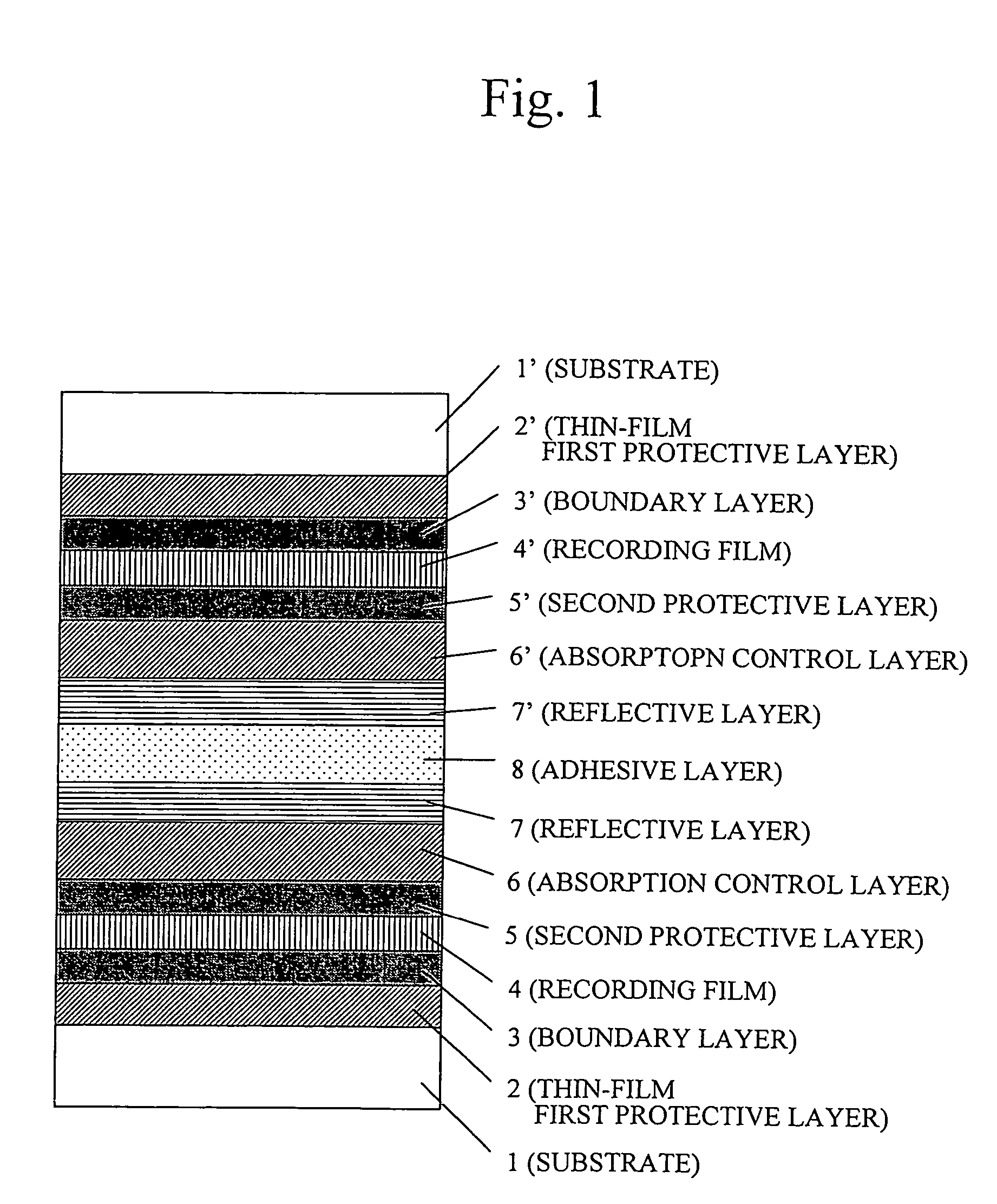
FIG. 1 is a cross section of the disc information recording medium according to a first embodiment of the invention, which was manufactured by the following process.

First, a first protective layer 2 comprising (MgF2)50(ZnS)50 was formed on a polycarbonate substrate 1 of a diameter 12 cm and a thickness 0.6 mm, to a film thickness of 30 nm. The substrate 1 was provided on the surface thereof tracking grooves of a track pitch of 0.615 microns for land / groove recording, and with a pit sequence at a position off the track center, i.e., substantially on an extension of the boundary between land and groove, the pit sequence indicating address information or the like. Then, a lower boundary layer 3 comprising a Cr2O3 film was formed to a thickness of 2 nm, followed by the sequential formation of a recording film 4 comprising Ge38.1Sb9.5Te52.4, a second protective layer 5 with a thickness of 8 nm an...

embodiment 2

A disc (Embodiment 2) was prepared that differed from the disc of Embodiment 1 only in the first protective layer, and the number of overwrites was measured in the same manner as in the case of Embodiment 1. The result showed that the number of overwrites can be increased even when the thickness of the disc is smaller than that of Embodiment 1.

In the first protective layer of Embodiment 2, a first protective layer 2 made of (MgO)60(SnO2)40 was formed to a thickness of 30 nm.

(Composition and Film Thickness of the First Protective Layer)

The change in reflectivity was determined after rewrites of 10000 times while changing the mole ratios of MgO and SnO2 in the material of the first protective layer. As the film formation rate changes depending on the amount of MgF2, the ratio to (ZnS)80(SiO2)20 was determined. The results are shown in Table 6.

TABLE 6MgO contentChange in(mole %)reflectivity (mV)Film formation rate6202.510102.01581.72561.54031.26021.07510.99000.710000.2

The res...

embodiment 3

(COMPARATIVE EXAMPLE 1)

A disc (Comparative Example 1) was prepared that was identical to Embodiment 1 except that the first protective layer and the recording film were changed.

The first protective layer consisted of a (ZnS)80 (SiO2)20 film to a thickness of 130 nm. The recording film consisted of a Ge22Sb22Te56 film to a thickness of 8 nm. When the material cost for the first protective layer was compared in the same manner as in Embodiment 1, the result showed that the material cost was more than twice as much as that of Embodiment 1, as shown in FIG. 10.


PUM

PropertyMeasurementUnit
thicknessaaaaaaaaaa
thicknessaaaaaaaaaa
thicknessaaaaaaaaaa

Abstract

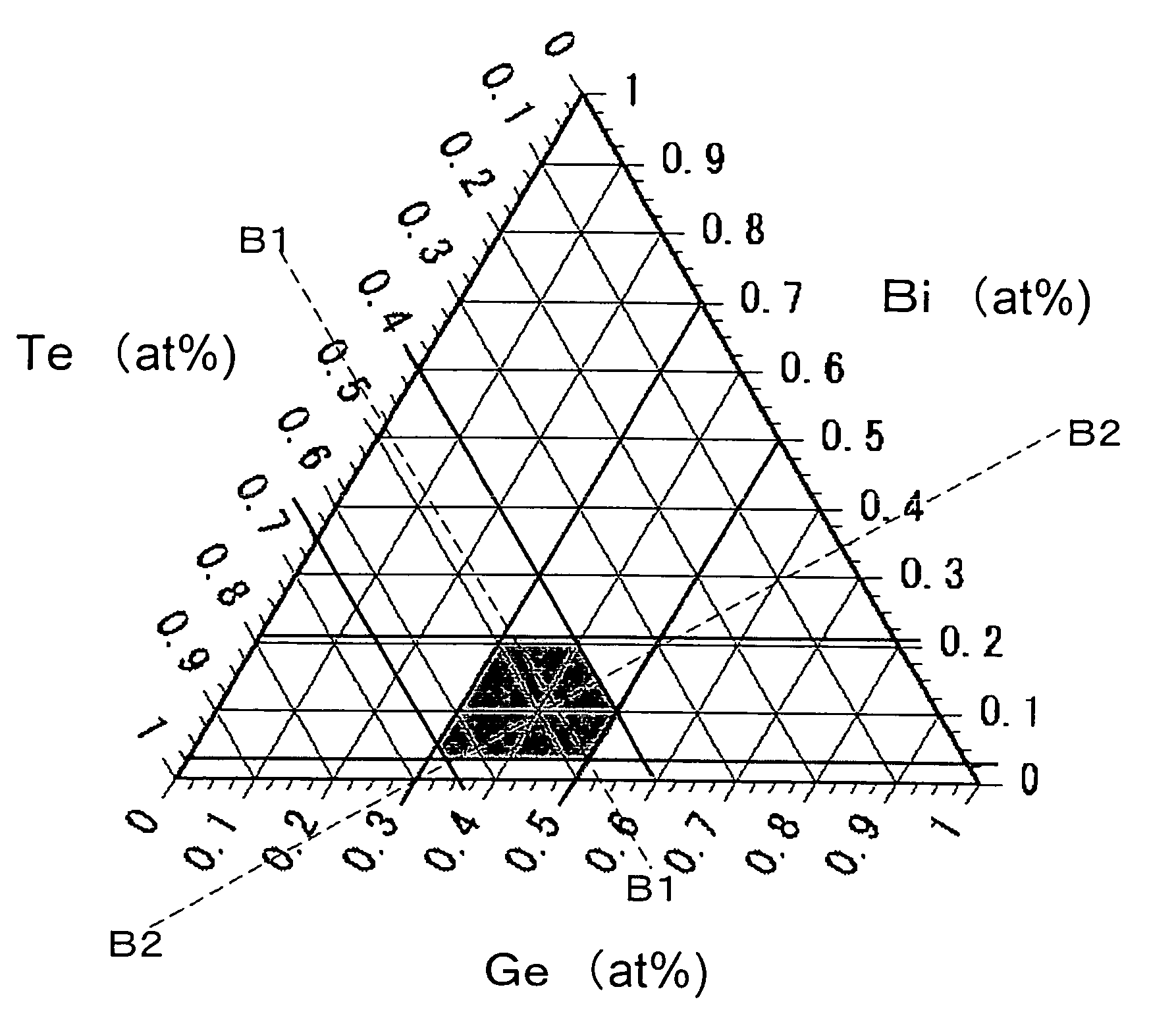
An information recording medium for high-density recording and reproduction that is low-cost and that has good rewrite characteristics. The information recording medium, in which recording is performed as an atomic arrangement is changed by optical irradiation, is capable of a number of rewrites. The information recording medium comprises a substrate on which a first protective layer with a thickness in the range from 18 to 65 nm, a recording film, a second protective layer, and a reflective layer are disposed in the mentioned order as seen from a light-incident side. Not less than 97 atomic % of the composition of the recording film is accounted for by Ge, Bi, and Te.

Description

CLAIM OF PRIORITY The present application claims priority from Japanese application JP 2004-077408 filed on Mar. 18, 2004, and Japanese application JP 2003-329298 filed on Sep. 22, 2003, the contents of which are hereby incorporated by reference into this application. BACKGROUND OF THE INVENTION 1. Field of the Invention The present invention relates to information recording media used for optical discs. 2. Background Art There are many variations of the principle of recording information on a thin film (recording film) by irradiating it with laser light. Among them, the techniques that utilize a change in atomic arrangement by laser light irradiation, such as a phase-change (also called a phase transition, or a phase transformation) of the film material, are advantageous because they do not involve a deformation of the thin film and therefore allow two disc members to be directly bonded to each other to obtain an information recording medium with a double-sided disc structure....

Claims


Application Information

Patent Timeline
Patent Type & Authority Applications(United States)
IPC IPC(8): B41M5/26C22C28/00G11B7/0045G11B7/24G11B7/2403G11B7/243G11B7/2433G11B7/2437G11B7/254G11B7/257
CPCG11B7/00454G11B7/2403G11B7/24067G11B2007/24316G11B7/257G11B2007/24312G11B2007/24314G11B7/243
Inventor HIROTSUNE, AKEMIUSHIYAMA, JUNKOANZAI, YUMIKO
Owner HITACHT MAXELL LTD
Learn More